Final Adjustments
3-24 Manual # 42-02-2M01 A1
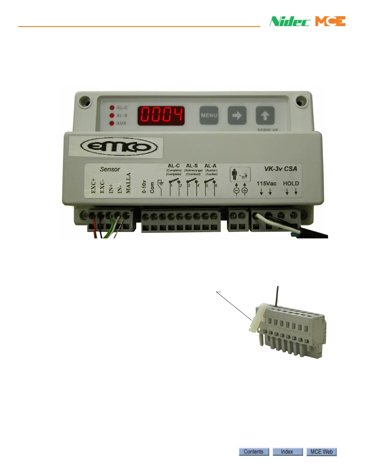
Installing the Control Unit
The control unit may be mounted using the DIN mounting bracket supplied or using the holes
in the unit itself. For 1:1 roping, the EMCO unit is mounted on the cartop. For 2:1 roping, the
EMCO unit is mounted in the controller cabinet.
1. EMCO control unit to cartop box (1:1 roping) or controller (2:1 roping):
• Connect one of the terminals directly below the 115Vac label to the controller 1 bus
• Connect the second terminal directly below the 115Vac label to the controller 2 bus
2. Sensor wires connect to the control unit as indicated on the wire:
• red wire to terminal EXC+
• black wire to terminal EXC-
• green wire to terminal IN+
• white wire to terminal IN-
• shield wire to terminal MALLA
Use the Terminal tool/key (wire insertion tool), or
a narrow flat blade screwdriver to open the detent
in the terminal connector to allow insertion of the
tinned wires.
For 2:1 roped units, route the sensor wires through the overhead to the machine room. The sen-
sor wires, which are only 6 feet in length, must be extended. Use a terminal block to join wire
lengths and route wires through conduit.