Installation
2-24 42-02-2M01 A1
CT E300 Drive Parameters
Set drive parameters using the drive keypad. If drive parameters are not correctly set, attempt-
ing to move the elevator can be VERY DANGEROUS
. MCE sets these parameters before ship-
ment, but you must check them at the site.
Drive parameters must be correctly set. If not, elevator control can be erratic and potentially DAN-
GEROUS. Never change drive parameters while the elevator is running.
• Read the drive manufacturer manual shipped with this controller. It provides essential
information about setting up the drive that cannot be included in the MCE manual. Follow
the Initial Start-up procedure described in the drive manufacturer manual.
• Read and follow the parameter settings in the table shipped with the controller from MCE.
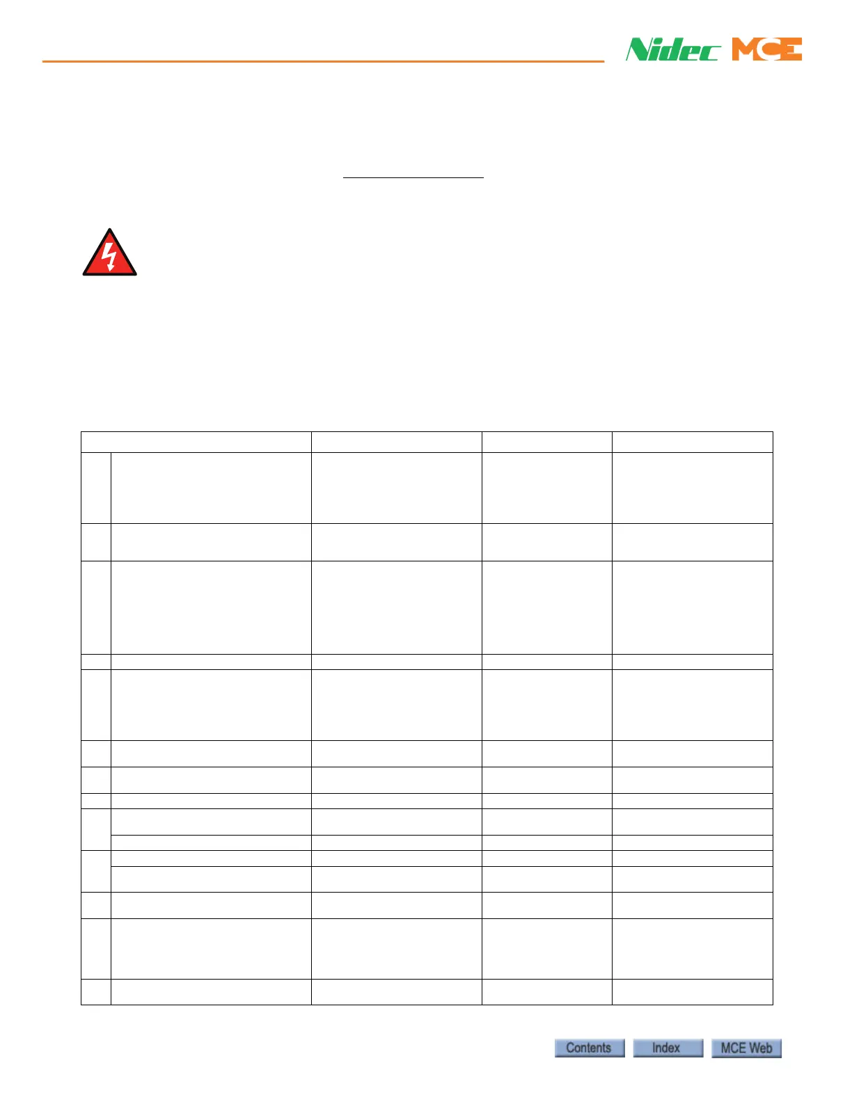
Table 2.3 Menu A User Menu
Parameter Description Range Default MCE Values
A01 User Security Status {H02}
User Menu A (0)
All Menus (1)
Read-only User Menu A (2),
Read-only (3)
Status Only (4)
No Access (5)
1=All Menus
A02 Drive Control Mode {B01}
Open loop (1),
RFC-A (2),
RFC-S (3)
Open loop (1)
RFC-A (2)
FRFC-S (3)
[job specific] 2=RFC-A (induc-
tion motor) 3=RFC-S (PM syn-
chronous motor)
A10 Control Input Mode {H11}
Analog Run Prmt (0)
Analog 2 Dir. (1)
Priority 1 Dir (2)
Binary 1 Dir (3)
Priority 2 Dir (4)
Binary 2 Dir (5)
Control Word (6)
DCP3 (7), DCP4 (8)
Priority 1 Dir (2) 0=Analog Run Prmit
A11 Direction Input Invert {H12} Off (0) or On (1) Off (0) Off (0)
A12 Drive Encoder Type {C01}
AB (0), FD (1), FD (2), AB Servo
(3), FD Servo (4), FR Servo (5),
SC (6) CSC Hyperface (7), EnDat
(8), SC EnDat (9) SSI (10), SC
SSI (11), SC Serco (12),SC Sc
(15)
AB (0)
AB Servo (3)
0=AB
9=SC EnDat
A13
Drive Encoder Auto Configuration
Select {C02}
Disabled (0) or Enabled (1) Enabled (1)
0=Disabled (AB)
1=Enabled (SC EnDat)
A14
Drive Encoder Rotary Pulses
Per Revolution {C03}
1 to 100,000 ppr
1024 ppr
4096 ppr
[encoder specific] (AB)
2048 (SC EnDat)
A15 Drive Encoder Voltage Selection {C04} 5V (0), 8V (1), 15V (2) 5V (0) [encoder specific]
A16
Position Feedback Phase Angle {C13}
0.0 to 359
o
0.0
o
[encoder specific] Only used for
PM synchronous motor
Slip Compensation Enable {B10} Off (0) or On (1) On (1)
A17
(CL) Drive Encoder Feedback {C12} Off (0) or On (1) Off (0) Off (0)
(OL) Low Frequency Voltage Boost
{B12}
0.0 to 12.0% 3% 3%
A18 Motor Rated Current {B02} +VM_RATED_CURRENT A
Maximum Heavy Duty
Rating (J05)
[motor-specific]
A19 Motor Rated Voltage {B03} +VM_AC_VOLTAGE_SET V
200 v drive: 300V
50Hz-400 V drive: 400V
60Hz-400 V drive: 460 V
575 V drive: 575 V
690 V drive: 690V
[motor-specific]
A20 Number of Motor Poles {B05} Automatic (0) to 480 Poles (240)
Automatic (0)
16 Poles (3)
[motor specific] 6 poles for
induction motor
 Loading...


