Installation
2-34 42-02-2M01 A1
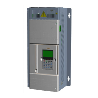
Verify Motor Rotation, Control Techniques E300
1. Move the elevator on Inspection and verify that the motor is under control and rotating
in the proper direction. Verify output current at parameter A04{J22} on the drive.
2. If the motor is rotating under control in the proper direction while drawing nominal
current (30-40% of motor FLA), skip the remaining steps.
• If the motor draws nominal current and rotates in the opposite direction, change the
commanded speed polarity by changing parameter T31 from 0 to 1 or 1 to 0.
• If the motor runs away or draws excessive current (near or above motor FLA) while not
moving at all, swap any two motor leads. Then, repeat from Auto Tune Motor Data,
Control Techniques E300 section.
If the motor still draws excessive current and does not rotate, swap the two motor leads again
and perform the motor autotune again. If the motor still draws excessive current and doesn't
turn, the autotune process was unable to align the encoder. In this case, change Minimum
Movement Phasing Test Angle parameter B54 to 0.01. Then repeat steps from Auto Tune Motor
Data section.
Verify Motor Speed, Control Techniques E300
While moving on Inspection, verify with a hand-held tachometer and the speed displayed on
the controller’s F3 > Controller System menu.
The default speed loop gains may not be set at the optimum value. Even though the values will
be system dependent, reasonable initial values should be within the following range:
• a. A49{I01} – 0.1 to 0.5 s/rad (RFC-S) or 0.01 to 0.05 s/rad (RFC-A)
• b. A50{I02} – 1.0 to 5.0 s2/rad (RFC-S) or 0.1 to 0.5 s2/rad (RFC-A)
• c. A51{I05} – 2.0 to 10.0 ms
• d. A52{I06} – Set to A49{I01} value
• e. A53{I07} – Set to A50{I02} value
• f. A54{I10} – Set to A51{I05} value
If the car is not running at inspection speed, verify the following the following parameters on
the drive:
1. Check the Inspection Speed setting (F7:155)
2. Check F7:141 Profile Scaling at 100%
3. Check Nominal Elevator Speed mm/s setting (A28{E01})
4. Check Traction Sheave Diameter setting (A29{E02})
5. Check Roping Setting (A30{E03})
6. Check Gear Ratio Numerator (A31{E04})
7. Check Gear Ratio Denominator (A32{E05})
To adjust the speed of the elevator, perform the following:
Geared: Adjust the Gear Ratio Numerator parameter A31{E04}. Increase this value to
increase the elevator’s speed. The Nominal Elevator Speed RPM parameter A33{E07} will be
automatically adjusted as A31{E04} is altered. The parameters A28{E01}, A29{E02},
A30{E03}, A31{E04}, and A32{E05} should have been initially adjusted in the order shown to
maintain correlation between them.
 Loading...
