3 Electrical Connection
BU 0210 en-3117 13
3 Electrical Connection
Pos: 34 /A nl eitu nge n/El ek tro nik/FU u nd S tart er/ 1. Allg emei n es/Si ch erhei ts- und Inst all ati onshi n weis e/Si cher hei tshi n weis e/ver sc hie den e/W ARNU NG - El ektri sc her Schl ag ( nic ht unter Sp ann ung ar beit en) @ 1 4\mod_1480331381423_388.docx @ 2308485 @ @ 1
Electric shock
Touching electrically conducting components may cause an electric shock and severe or possibly fatal injury.
• Disconnect the frequency inverter from the power supply before starting installation work.
• Only work on devices which have been disconnected from the power supply.
Pos: 35 /A nl eitu nge n/El ek tro nik/FU u nd S tart er/ 1. Allg emei n es/Si ch erhei ts- und Inst all ati onshi n weis e/Si cher hei tshi n weis e/ver sc hie den e/W ARNU NG - El ektri sc her Schl ag ( War tez eit) @ 14\mod_1480332099956_388.docx @ 2308520 @ @ 1
Electric shock
The frequency inverter carries hazardous voltage for up to 5 minutes after being switched off.
• Only start work after a waiting period of at least 5 minutes after switching off the mains supply
(disconnection).
Pos: 36 /Anlei tunge n/Ele ktro nik/PO SICON /3. Ele ktri scher Ans chl uss/!El ektri scher Ansc hluss_T ext @ 14\mod_1480332306236_388.docx @ 2308555 @ @ 1
Position control by the frequency inverter can only be used if it receives immediate feedback of the
current position of the drive unit.
An encoder is usually used to detect the current position.
Pos: 37 /Anlei tunge n/Ele ktro nik/PO SICON /3. Ele ktri scher Ans chl uss/An schl uss am G erät SK 20 0E ... SK 235 E [SK 2 xxE] @ 14\mod_1480337880039_388.docx @ 2308590 @ 2 @ 1
3.1 Connection to SK 200E … SK 235E frequency inverters
Pos: 38 /A nl eitu nge n/El ek tro nik/FU u nd S tart er/ 2. M o ntag e un d Ins tall ati on/ El ektri sc her Ansc hluss /Ele ktrisc her Ans chluss _Er gänzu ng1 [SK 2 xxE] @ 7\ mod_1434463656020_388.docx @ 226135 @ @ 1
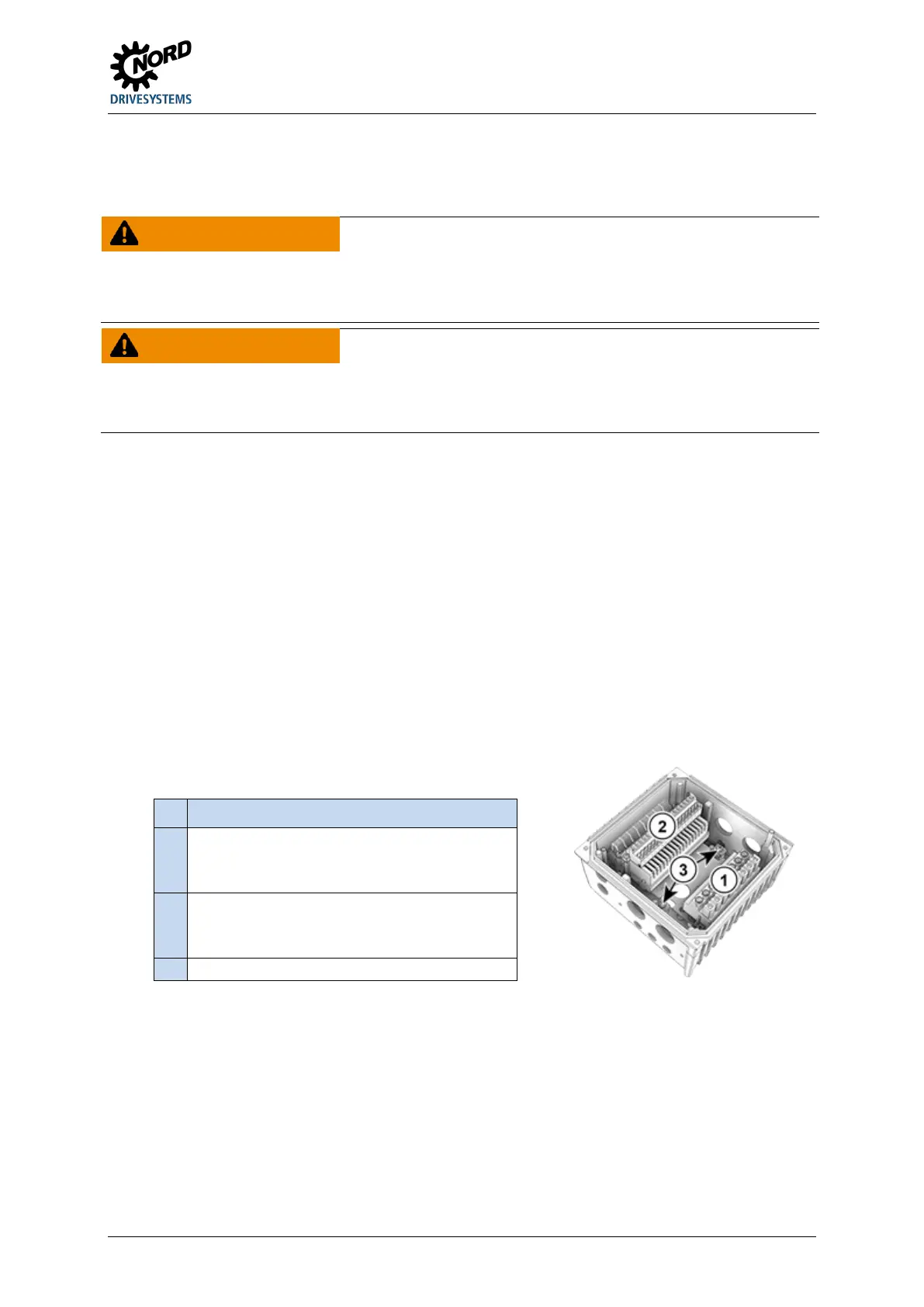
In order to access the electrical connections, the SK 2xxE must be removed from the SK TI4-…
connection unit ( Section ).
One terminal block is provided for the power connections and one for the control connections.
The PE connections (device-earth) are inside the cast housing of the connecting unit on the base. A
contact is available on the power terminal block for size 4.
Pos: 39 /A nl eitu nge n/El ek tro nik/FU u nd Start er/2. Mont age und Ins tall ation/ Ele ktrisc her Ansc hluss /Ele ktrisc her Ans chluss _Er gänzu ng2 [SK 1 xxE, SK 2xxE] @ 8\ mod_1439219159130_388.docx @ 236273 @ @ 1
The terminal strip assignments differ according to the version of the device. The correct assignment
can be found on the inscription on the respective terminal or the terminal overview plan printed inside
the device.
Pos: 40 /Anlei tunge n/Ele ktro nik/FU und Start er/2. Mont age und Ins tall ation/ Ele ktrisc her Ansc hluss /Ele ktrisc her Ans chluss _Er gänzung3 [SK 2 xxE] @ 8\mod_1439287784030_388.docx @ 236373 @ @ 1
Connecting terminals for
PE
Pos: 41 /Allgemein/Allgemeingülti ge M od ule/---------S eitenum bruch k ompa kt --------- @ 13\mod_1476369695906_0.docx @ 2265495 @ @ 1
 Loading...


