4 Function description
BU 0210 en-3117 35
Pos: 14 6 /Anlei tu nge n/El ektr oni k/P OSI CON /4. Fun kti ons besc hr eibung / Wego pti mal e Po siti oni erung _Er gä nz ung _02 _Beis pi el f ür ei ne M ult it urnanwendung @ 14\mod_1478171703235_388.docx @ 2301105 @ 5 @ 1
Examples for a "multiturn application"
The calculation of the overflow point of a multiturn application is made according to the following
equation:
The following example is for a speed ratio or reduction ratio of "1". The total path is 101 revolutions of
the encoder. The maximum value of the position or the overflow point is calculated as follows:
±n
max
= 0,5 * U
D
* Ü
b
/ U
n
n
max
: Number of revolutions of motor = Overflow point
(P615)
Ü
b
: Speed ratio
(P607 [-xx])
U
n
: Reduction ratio
(P608 [-xx])
U
D
: Number of revolutions of the encoder for one revolution of the application
1)
Depending on the encoder or absolute encoder used for positioning control: [-xx] = [-02]
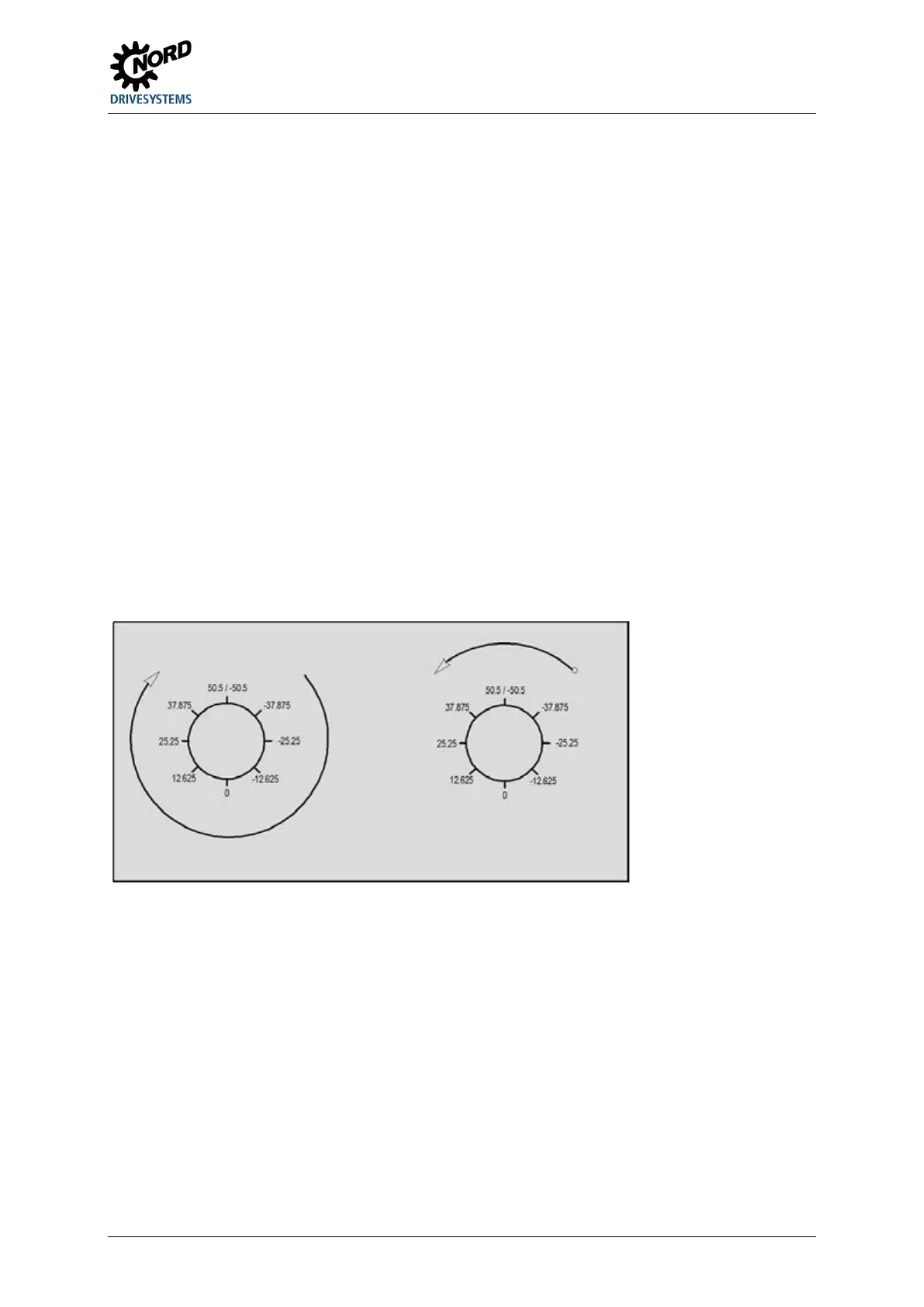
Example 1
The encoder, an absolute encoder, is mounted on the motor shaft (speed and reduction ratio = "1").
The total path is 101 revolutions of the encoder.
±n
max
= 0.5 * 101 * 1 / 1 = 50.5 revolutions
The following values are parameterised:
P607 [-02]
= 1
= 1
P615 =
= 50.5
Figure 2: Rotary platform positioning with a multiturn application
Example 2
The encoder, an absolute encoder is installed on the output side of the gear unit. The gear unit has a
speed ratio of i = 26.3. The total path is 101 revolutions of the encoder.
±n
max
= 0.5 * 101 * 263 / 10 = 1328.15 revolutions
The following values are parameterised:
P607 [-02]
= 263
= 10
P615 =
= 1328.15
Pos: 14 7 /Allg emein/ Allg emeing ültig e Mod ule/---------Sei tenumbr uch ko mpakt --------- @ 13\mod_1476369695906_0.docx @ 2265495 @ @ 1
 Loading...


