POSICON positioning control – Supplementary manual for series SK 200E and SK 250E-FDS
34 BU 0210 en-3117
Pos: 14 4 /Anlei tung en/El ektr onik/P OSICON /4. Funkti onsbes chr eibung/ Wego ptimal e Posi tioni erung _Ergä nzung _01 _Beispi el für ei ne Singleturnanwendung @ 14\mod_1478169580383_388.docx @ 2301069 @ 5 @ 1
Examples for a "single-turn application"
The calculation of the overflow point of a single-turn application is made according to the following
equation:
±n
max
= 0.5 * Ü
b
/ U
n
n
max
: Number of revolutions of motor = Overflow point
(P615)
Ü
b
: Speed ratio
(P607 [-xx])
U
n
: Reduction ratio
(P608 [-xx])
)
Depending on the encoder or absolute encoder used for positioning control: [-xx] = [-02]
Example 1
The encoder, an absolute encoder, is mounted on the motor shaft (speed and reduction ratio = "1").
±n
max
= 0.5 * 1 / 1 = 0.5 revolutions
The following values are parameterised:
= 1
P608 [-02]
= 1
=
= 0.5
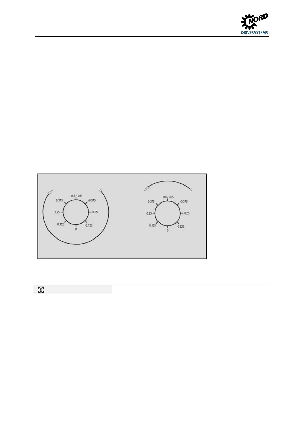
Linear path Path optimised movement
Figure 1: Rotary platform positioning with a single-turn application
In this case (single-turn application, encoder on the motor shaft) P615 can also remain in the factory setting
(setting 0).
Example 2
The encoder, an absolute encoder is installed on the output side of the gear unit. The gear unit has a
speed ratio of i = 26.3.
±n
max
= 0.5 * 263 / 10 = 13.15 revolutions
The following values are parameterised:
P607 [-02]
= 263
= 10
P615 =
= 13.15
Pos: 14 5 /Allg emein/ Allg emeing ültig e Mod ule/---------Sei tenumbr uch ko mpakt --------- @ 13\mod_1476369695906_0.docx @ 2265495 @ @ 1
 Loading...


