3 Electrical Connection
BU 0210 en-3117 23
Pos: 72 /A nl eitu nge n/El ek tro nik/FU u nd S tart er/ 2. M o ntag e un d Ins tall ati on/ El ektri sc her Ansc hlus s/D re hge ber/F arb- und Kont akt bel egu ng f ür I nkre men tal dre hge ber ( HTL) [S K 2xxE ] @ 1 \mod_1342601381353_388.docx @ 33747 @ 3 @ 1
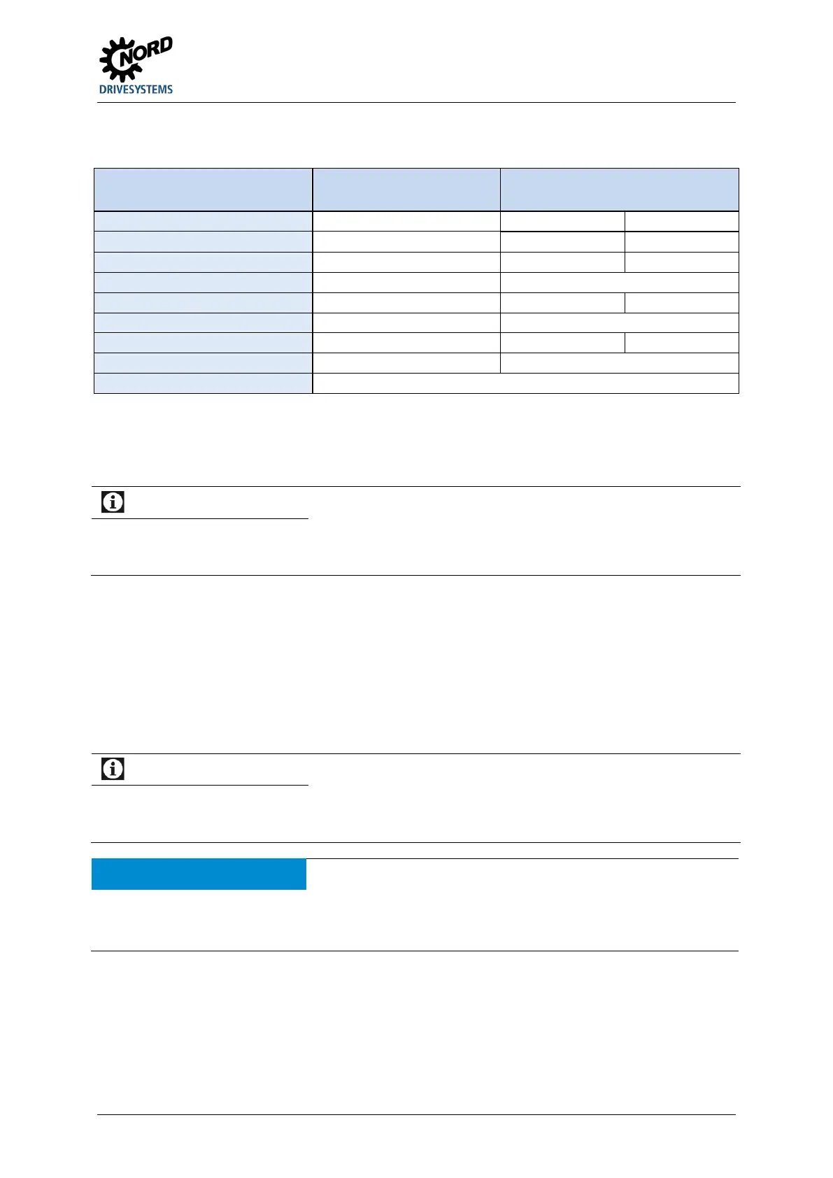
3.3.2 Colour and contact assignments for the incremental encoder (HTL)
Function
Wire colours,
for incremental encoder
Assignment for SK 2xxE
Track A brown 22 DIN2
Track B inverse (B /) pink --
Track 0 inverse black --
Wide-area connection to frequency inverter housing.
Only digital inputs DIN 2 and DIN 3 are in a position to process the signals of an HTL encoder. For the
use of an encoder, parameters (P300) or (P600) must be activated according to requirements (speed
feedback / servo mode or positioning).
Information
DIN 2 and DIN 3 double allocation
When an encoder is being used, digital inputs DIN 2 and DIN 3 must be deactivated using an OR operation of the
parametrised functionality and the encoder evaluation that are always active in the inverter (parameter P420 [-02,
-03]) or using DIP switches ).
NOTE:
Attention must be paid to the data sheet enclosed with the encoder.
RECOMMENDATION:
For high reliability of operation, particularly with long connecting cables, an
incremental encoder for 1030 V supply voltage must be used. An external or
internal 24V voltage from the frequency inverter can be used as the voltage
supply. 5
V encoders should not be used! If a power supply of type
SK-xU4-24V… is being used, attention must be paid to the power restriction
of the power supply (encoder power consumption: up to 150 mA).
Rotation direction
The direction of rotation of the incremental encoder must correspond to that of the motor. Therefore, depending
on the rotation direction of the encoder to the motor (possibly reversed), a negative number must be set in
parameter P301.
Encoder signal faults
Cores that are not required (e.g. track A inverse / B inverse) must be insulated.
Otherwise, if these cores come into contact with each other or the cable shield, short-circuits can occur that can
lead to encoder signal problems or destruction of the encoder.
Pos: 73 /A nl eitu nge n/El ek tro nik/FU u nd S tart er/ 2. M o ntag e un d Ins tall ati on/ El ektri sc her Ansc hlus s/D re hge ber/F arb- und Ko nt aktbel eg ung für In krem ental dr ehg eber (HTL)_Ergänzung [SK 2xxE] @ 11\mod_1458311618705_388.docx @ 314437 @ @ 1
If the rotary encoder has a zero track, this must be connected to digital input 1 of the device. The zero
track is read out by the frequency inverter if parameter P420 [-01] has been set to function "43".
Pos: 74 /A llg em ein/ Allg em eing ülti ge M od ule/ ---------Seite numbruc h kom pakt --------- @ 13\ mod_1476369695906_0.docx @ 2265495 @ @ 1
 Loading...


