3 Electrical Connection
BU 0210 en-3117 21
Pos: 59 /A nl eitu nge n/El ek tro nik/FU u nd S tart er/ 2. M ont age und Ins tall ation/ Ele ktrisc her Ansc hluss /SK 1 xxE, SK 2x xE, SK xx xE-FD S/Steu ertei l/De tails St euer anschl üsse [SK xxxE-F DS] @ 11\ mod_1466081350464_388.docx @ 329741 @ 3 @ 1
3.2.2 Control connection details
Pos: 60 /A nl eitu nge n/El ek tro nik/FU u nd S tart er/ 2. M ont age und Ins tall ation/ Ele ktrisc her Ansc hluss /SK 1 xxE, SK 2x xE, SK xx xE-FD S/Steu ertei l/De tails St euer anschl üsse (S ammlu ng)/D etail s Steuer ans chlüss e_0 0_Tabel lenk opf_[S K xxxE-F DS] @ 1 1\mod_1466081544267_388.docx @ 329795 @ @ 1
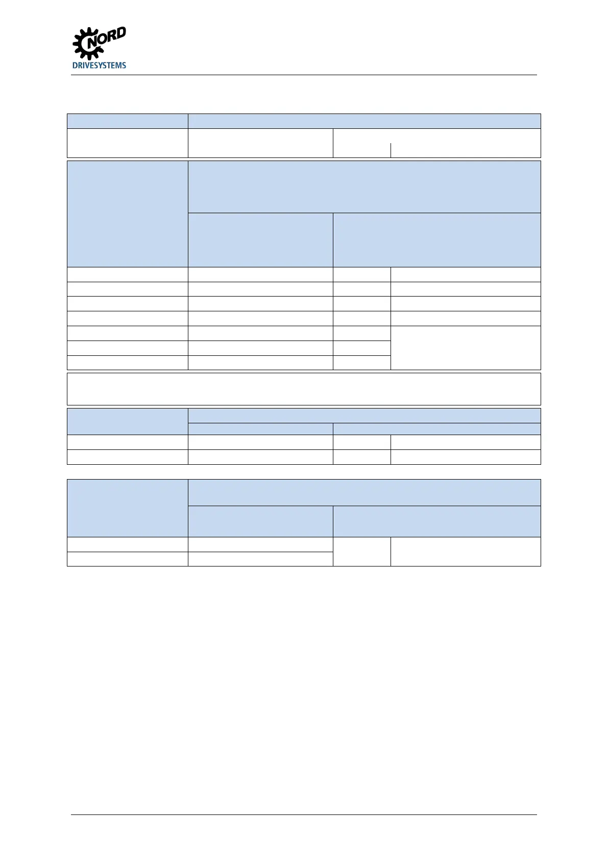
Description / Technical data
Function of factory setting
Pos: 61 /Anlei tunge n/Ele ktro nik/FU und Start er/2. Mont age und Ins tall ation/ Ele ktrisc her Ansc hluss /SK 1 xxE, SK 2x xE, SK xx xE-FDS/Steuerteil/Details Steuer ans chl üss e (S am mlung )/D etai ls Ste uer ans chl üss e_0 3_DIN [SK 2 xxE-FD S] @ 11 \mod_1466165916872_388.docx @ 330090 @ @ 1
Actuation of device via an external controller, switch or similar, connection of HTL
transmitter (DIN2 and DIN3 only)
The factory settings of digital inputs DIN5 to DIN7 depend on the configuration of
option slots H1 and H2.
DIN1-5 according to EN 61131-2, type 1
Low: 0-5 V (~ 9.5 kΩ)
High: 15-30 V (~ 2.5 - 3.5 kΩ)
Scan time: 1 ms
Reaction time: 4 - 5 ms
Input capacitance
10 nF (DIN1, DIN4, DIN5, DIN6, DIN7)
1.2 nF (DIN2, DIN3)
Limit frequency (only DIN2 and DIN3)
Min.: 250 Hz, Max.: 205 kHz
DIN2 Digital input 2 P420 [-02] No function
( Section "Configuration of
option slots on the control level")
DIN7 / AIN2 Digital input 7 P420 [-07]
Pos: 62 /Anlei tunge n/Ele ktro nik/FU und Start er/2. Mont age und Ins tall ation/ Ele ktrisc her Ansc hluss /SK 1 xxE, SK 2xxE, S K xxxE-FD S/ Steu ert eil /De tails St euer ans chl üss e (S am mlung )/D etai ls St euer ans chl üss e_0 3_DI N_Er gän zu ng [ SK 2 xxE-F DS] @ 12 \mod_1468393540628_388.docx @ 338440 @ @ 1
Digital inputs DIN6 and DIN7 depend directly on analogue inputs AIN1 and AIN2. This means that the digital functions can only be used if the
analogue functions are disabled (corresponding to the factory setting).
Pos: 63 /A nl eitu nge n/El ek tro nik/FU u nd S tart er/ 2. M o ntag e un d Ins tall ati on/ El ektri sc her Anschluss/S K 1xxE, SK 2xxE, SK xxxE-FDS/ Steu ert eil/D etai ls Ste uer ans chl üss e (S amml ung )/D etail s Ste uer ansc hlüs se_ 05_ Quel le Ste uers pan nung [S K xxxE- FDS] @ 11\mod_1466166080060_388.docx @ 330160 @ @ 1
Control voltage from the inverter, e.g. as power supply for accessories
24 V DC ± 25 %, short circuit-proof Maximum load
VO / 24V Voltage output - -
See "Total currents" information (
Pos: 64 /A nl eitu nge n/El ek tro nik/FU u nd S tarter /2. M ontag e und Inst allati on/El ektri scher Ansc hluss/S K 1xx E, SK 2xxE , SK xxxE-F DS/ Steuer teil /Detail s Ste uerans chlüs se (Sa mmlung )/De tails St euer anschl üss e_07_ SYS [SK 2 xxE-FD S] @ 11\ mod_1466166209620_388.docx @ 330230 @ @ 1
NORD-specific bus system for communicating with other devices (e.g. intelligent
option modules or frequency inverters)
Up to four frequency inverters (SK 2xxE,
SK 1x0E, SK 2xxE-FDS) can be operated
on a single system bus.
Address = 32 / 34 / 36 / 38
SYS L System bus- P514/515 250kBaud / Address 32
dec
Pos: 65 /A llg em ein/ Allg em eing ülti ge M od ule/ ---------Seite numbruc h kom pakt --------- @ 13\ mod_1476369695906_0.docx @ 2265495 @ @ 1
 Loading...


