POSICON positioning control – Supplementary manual for series SK 200E and SK 250E-FDS
20 BU 0210 en-3117
Pos: 56 /Anlei tunge n/Ele ktro nik/FU und Start er/2. Mont age und Ins tall ation/M ont age/FD S [SK x xxE-FDS ]/ Stec ker beleg ung M 12- Stec kver bind er_ 01 [ SK xx xE-FDS] @ 11\mod_1465468996785_388.docx @ 328455 @ 5 @ 1
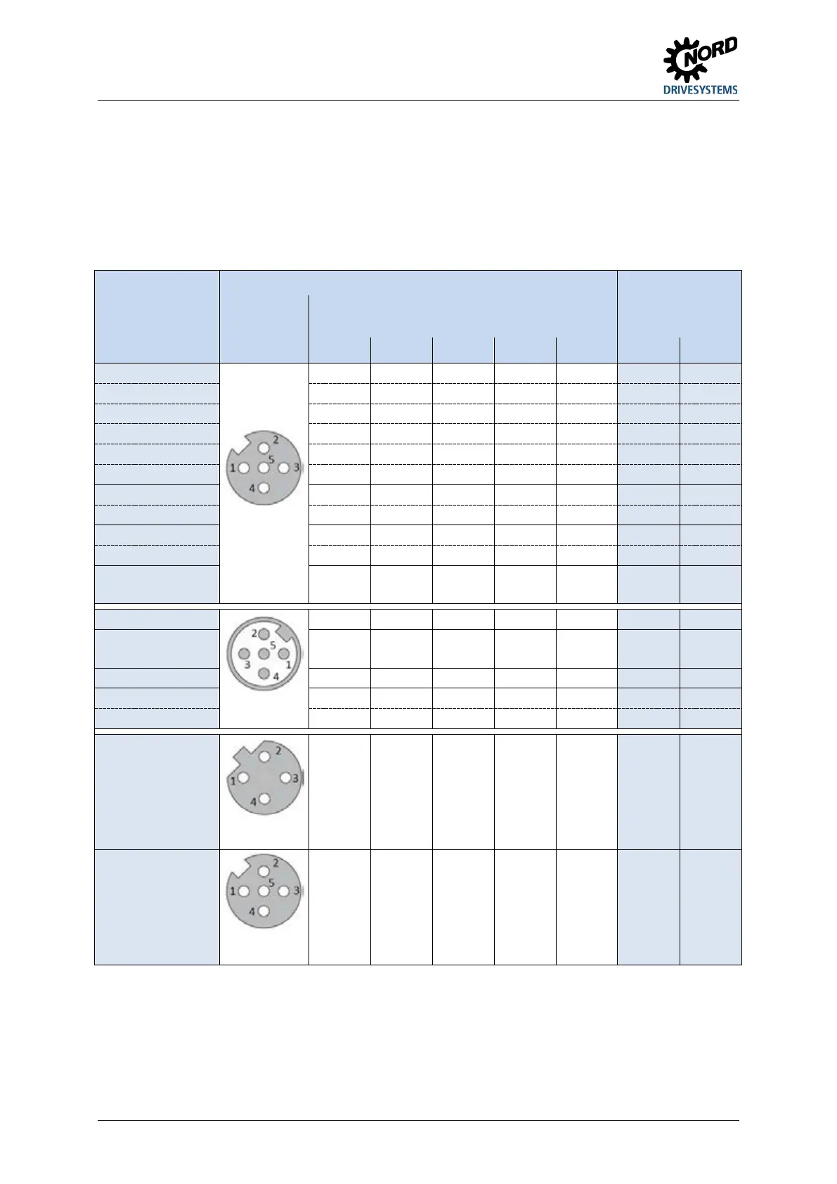
Plug connections for M12 plug connectors
Depending on the function, 5-pin M12 surface mounted plug connectors with coloured sockets or plug
inserts are installed. The colours reflect the functional assignment of the plug connector and therefore
enable easy identification on the FI. The same applies for the colour coding of the cover caps.
The following plug connectors may be used on the device, depending on the customer's specification.
Pos: 57 /Anlei tunge n/Ele ktro nik/FU und Start er/2. Mont age und Ins tall ation/M ont age/FD S [SK x xxE-FDS ]/ Stec ker beleg ung M 12- Stec kverbi nd er_ 02 [ SK 2 xxE- FDS ] @ 11\mod_1465472555767_388.docx @ 328489 @ 5 @ 1
Option slots M1 to M8
Function Plug connectors Option slot
Contact
diagram
Contact assignments
1 2 3 4 5 No. Colour
socket,
A-coded
DIN2 / DIN3 24 V DIN3 GND DIN2 PE M5 black
DIN4 24 V GND DIN4 PE M2 black
DOUT1 / DOUT2 24 V DOUT2 GND DOUT1 PE M3 black
AIN1 / AIN2 24 V AIN2 GND AIN1 +10 V
Ref
M7 white
Ref
or SYS+
or SYS-
plug,
A-coded
or SYS+
or SYS-
ASI ASI+ ASI- M8 yellow
socket,
B-coded
socket,
A-coded
Pos: 58 /A llg em ein/ Allg em eing ülti ge M od ule/ ---------Seite numbruc h kom pakt --------- @ 13\ mod_1476369695906_0.docx @ 2265495 @ @ 1
 Loading...

