3 Electrical Connection
BU 0210 en-3117 19
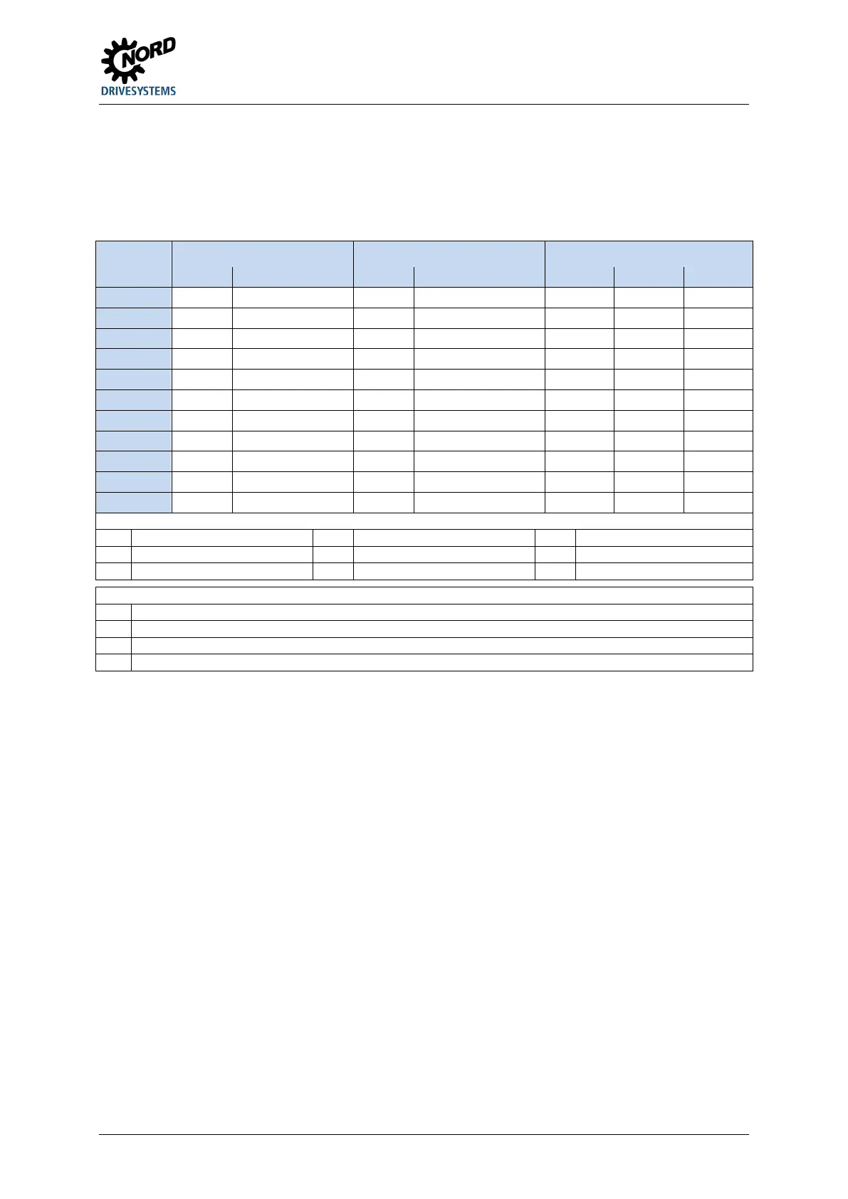
The control elements for the FI are located at the option slots H1 and H2.
The various types of control elements can be selected. Depending on the combination which is
selected, these have an effect on the function of the individual digital inputs. These functions are taken
into account in the factory settings of the relevant parameters for the specific frequency inverter.
Version Option slot H1
1)
Option slot H2
2)
Parameter function
3)
2 I L - A - R 4 / - Q {34} {33} {12}
7 II A - H II Sp1 - Sp2 {0} {33} {12}
Manual mode enabled, left
R
Manual mode enabled, right
Off
Manual mode not enabled
On
Manual mode enabled
Speed 1 (value from P113 [-01])
Speed 2 (value from P113 [-02])
Acknowledge fault
Switch (left – centre – right), locking, switch or key switch version
Switch (centre – right), locking, switch or key switch version
III Switch (left – centre – right), locking at centre and right, switch or key switch version
4 Pushbutton
Influences the parameter functions of digital inputs DIN 6 / 7
Influences the parameter functions of digital inputs DIN 5 / 7
Variants for which the parameter functions are configured to the value {0} do not have a functional effect on the corresponding digital input.
In such cases corresponding analogue functions can be assigned via the relevant alternative analogue inputs (see previous table).
Pos: 55 /A llg em ein/ Allg em eing ülti ge M od ule/ ---------Seite numbruc h kom pakt --------- @ 13\ mod_1476369695906_0.docx @ 2265495 @ @ 1
 Loading...

