POSICON positioning control – Supplementary manual for series SK 200E and SK 250E-FDS
24 BU 0210 en-3117
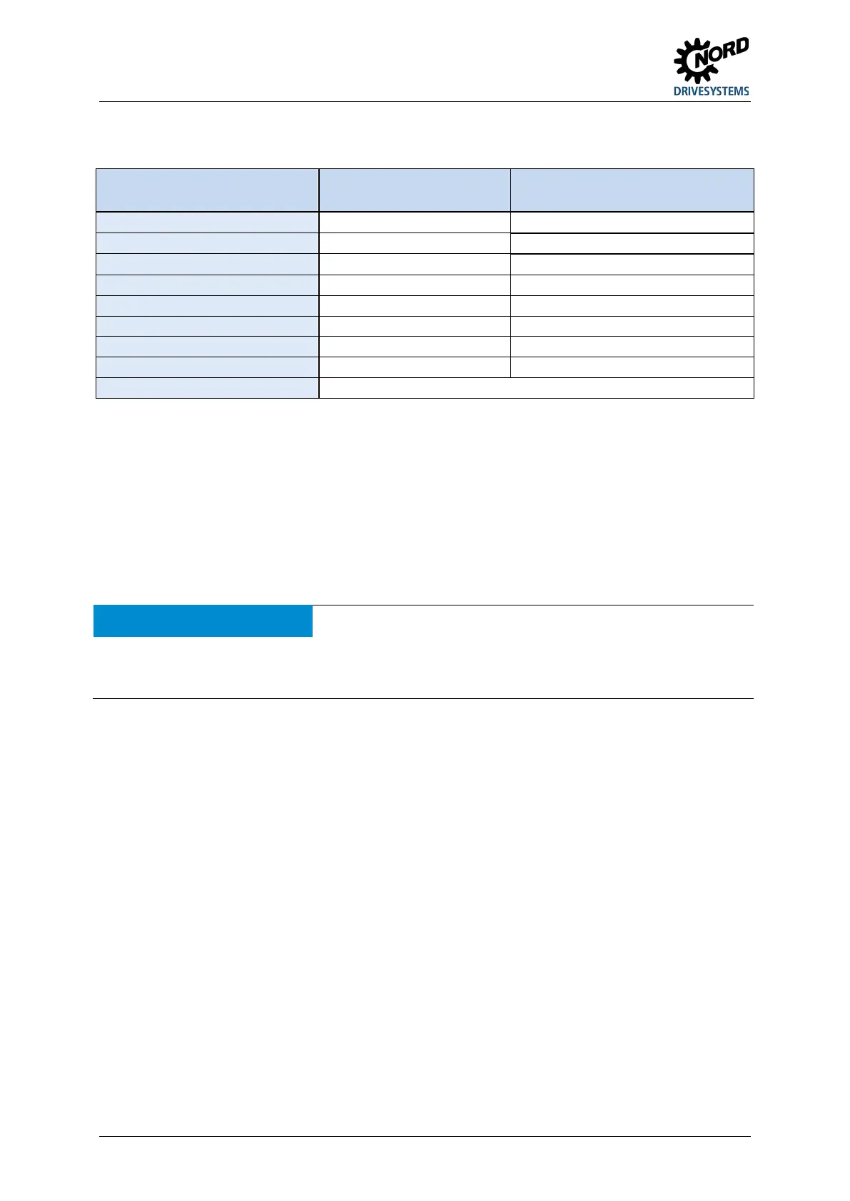
Pos: 75 /A nl eitu nge n/El ek tro nik/FU u nd S tart er/ 2. M o ntag e un d Ins tall ati on/ El ektri sc her Ansc hlus s/D re hgeber /F arb- und K ont a ktbel egu ng f ür I nkre men tal dre hge ber (HT L) [ SK 2xxE-F DS] @ 12\mod_1466419046760_388.docx @ 330439 @ 3 @ 1
3.3.3 Colour and contact assignments for the incremental encoder (HTL)
Function
Wire colours,
for incremental encoders
Assignment for SK 2xxE-FDS
Track B inverse (B /) pink
Connect to the "PE" contact of the plug connector.
For the use of an encoder, parameters (P300) or (P600) must be activated according to requirements
(speed feedback / servo mode or positioning).
NOTE:
Attention must be paid to the data sheet enclosed with the encoder.
RECOMMENDATION:
Incremental encoders with a supply voltage of 10 – 30 V must be used. An
external or internal 24V voltage can be used as the power supply. If the
device option HVS... (integrated mains unit) is used, the power limit of the
mains unit must be observed (encoder current consumption: up to 150 mA).
NOTICE
Encoder signal faults
Conductors that are not required (e.g. track A inverse / B inverse) must be insulated.
Otherwise, if these conductors come into contact with each other or the cable shield, short-circuits may occur
which result in encoder signal problems or destruction of the encoder.
Pos: 11 8 /Anlei tung en/El ektr onik/P OSICON /4. Funkti onsbes chr eibung /! Fun kti onsb esc hrei bung @ 14\ mod_1478004428994_388.docx @ 2299445 @ 1 @ 1
 Loading...


