4 Function description
BU 0210 en-3117 29
The CAN baud rate set in the encoder must be identical to the parameter P514 "CAN Baud Rate" and
all other participants in the bus system.
If parameterisation of the encoder is carried out via the frequency inverter, the transmission cycle for
the absolute encoder position is simultaneously set via the baud rate.
For the operation of several CANopen absolute encoders on a bus system, e.g. for synchronous
operation, different transmission cycle times can be set for the bus master and the CANopen absolute
encoders.
With the parameter P552 "CAN Master Cycle Time" the cycle time for the CAN/CANopen master
mode can be parameterised in Array [-01] and for the CANopen absolute encoder in Array [-02]. Care
must be taken that the parameterised values are not lower than the values in the column for the
minimum values of the actual cycle time. This valued depends on (P514).
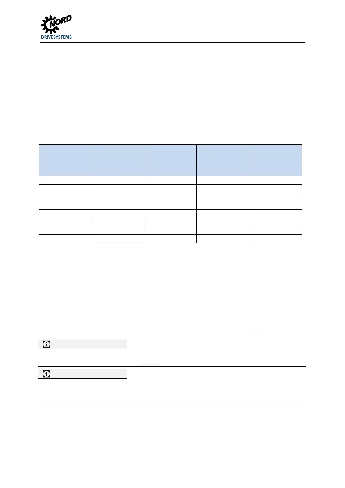
P514 P552[-01]
1)
P552[-02]
1)
t
Z
2)
Bus load
3)
Bus Master CANopen encoder
[kBaud] [ms] [ms] [ms] [%]
50 10 10 5 17.0
1000
5 2 1 4.25
Resulting factory setting
Minimum value for actual cycle time
3 Resulting from an encoder
Table 2: CANopen encoder cycle time dependent on the baud rate
The possible bus load in the system always depends on the real-time specific to the system. Very
good results are achieved with a bus load less than 40 %. Under no circumstances should a bus load
greater than 80 % be selected. For the estimation of the bus load, the other possible bus traffic
(setpoint and actual values for the frequency inverters and other bus participants) should also be
taken into account.
Additional explanations about the CAN interface can be obtained from Manual BU 2500
.
Pos: 128 /A nleit ung en/El e ktr onik /POS ICON /4. F unk tio nsbes chr eib ung/ Erg änz en de Ei nst ell ung en - C ANo pen Abs olut wer tge ber _Erg änz u ng_ 01_(I nfo DI P-Sc halter) [BU 021 0] @ 14\mod_1478092715927_388.docx @ 2300433 @ @ 1
Alternative to P514 and P515
As an alternative to setting via the parameters P514 and P515 the baud rate and the address can be set with the
DIP switches of the frequency inverter ( BU 0200
).
Pos: 129 /A nleit ung en/El e ktr onik /POS ICON /4. F unk tio nsbes chr eib ung/ Erg änz en de Ei nst ell ung en - C ANope n Absol utwer tgeb er_Erg änz ung_ 02_(I nfo IO-Erweit erung) [BU 021 0] @ 14\mod_1478096624597_388.docx @ 2300574 @ @ 1
The address ranges 10 to 13 and 20 to 23 are occupied by the optional IO extension (e.g. SK TU4-IOE). If such
modules are used in the bus system, these addresses can therefore not be used for the addressing of a
CANopen absolute encoder.
 Loading...


