Northstar Explorer 650 Installation and Operation Manual72
Power/data cable
Pin Wire Function
1 Black Ground: - power in, NMEA ground. (The cable has two black wires which are
connected inside the cable and it does not matter which black wire you use)
2 Brown Power out, 9 V DC (not used)
3 White NMEA out
4 Blue NavBus-
5 Red + power in, 10.5 to 30.5 V DC
6 Orange NavBus+
7 Yellow Auto power in
8 Green External alarm out, 30 V DC 200 mA maximum.
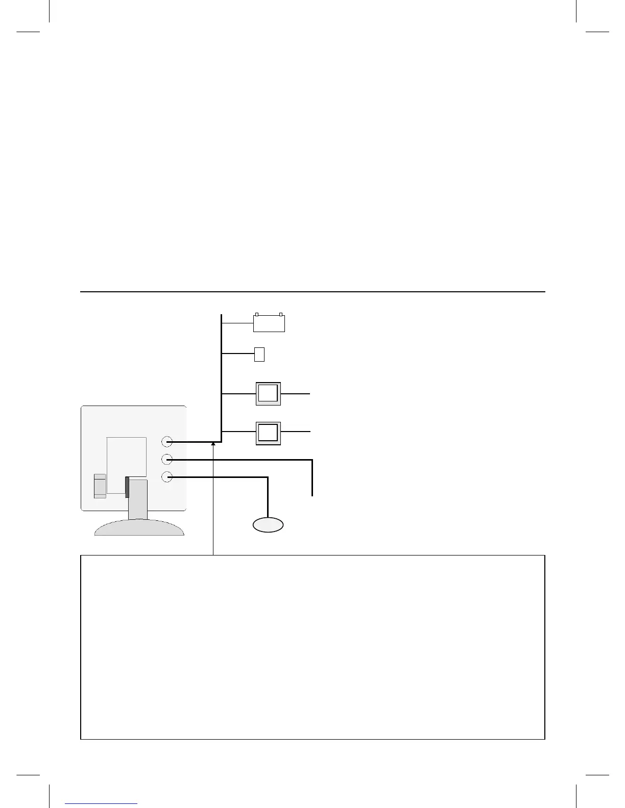
Connections
Display unit
(18-3)
Power (18-4)
Blue
Optional sensors and instruments
External alarms: Lights or sounders in the boat
to sound alarms through the boat (see section
18-4).
GPS or DGPS antenna: For GPS navigation, see
section 18-5.
Sonar transducer: For depth sounding and fish
finding, see section 18-6.
Fuel sensors: For fuel functions. The Explorer can
use these optional fuel flow sensors, fitted to one
or two engines:
• Northstar petrol/gasoline sensors (see
section 18-7)
• SmartCraft fuel sensors (see section 18-9)
DSC VHF radio: Tracks other boats with GPS
receivers and DSC radios and displays barometric
pressure (see section 18-8).
SmartCraft: With one or two SmartCraft capable
Mercury petrol/gasoline engines, the Explorer
can display engine data and trim and can control
troll speed (see section 18-9).
Other instruments: The Explorer can receive
data from other instruments and send data
to other instruments by NavBus or NMEA (see
sections 18-10 and 18-11).
Please consult your Northstar dealer for more
information.
External alarms (18-4)
NavBus instruments (18-10) and VHF radio (18-8)
NMEA out to instruments (18-11)
GPS antenna (18-5),
Petrol/gasoline sensors (18-7),
NMEA in (18-11)
Sonar transducer (18-6)