10
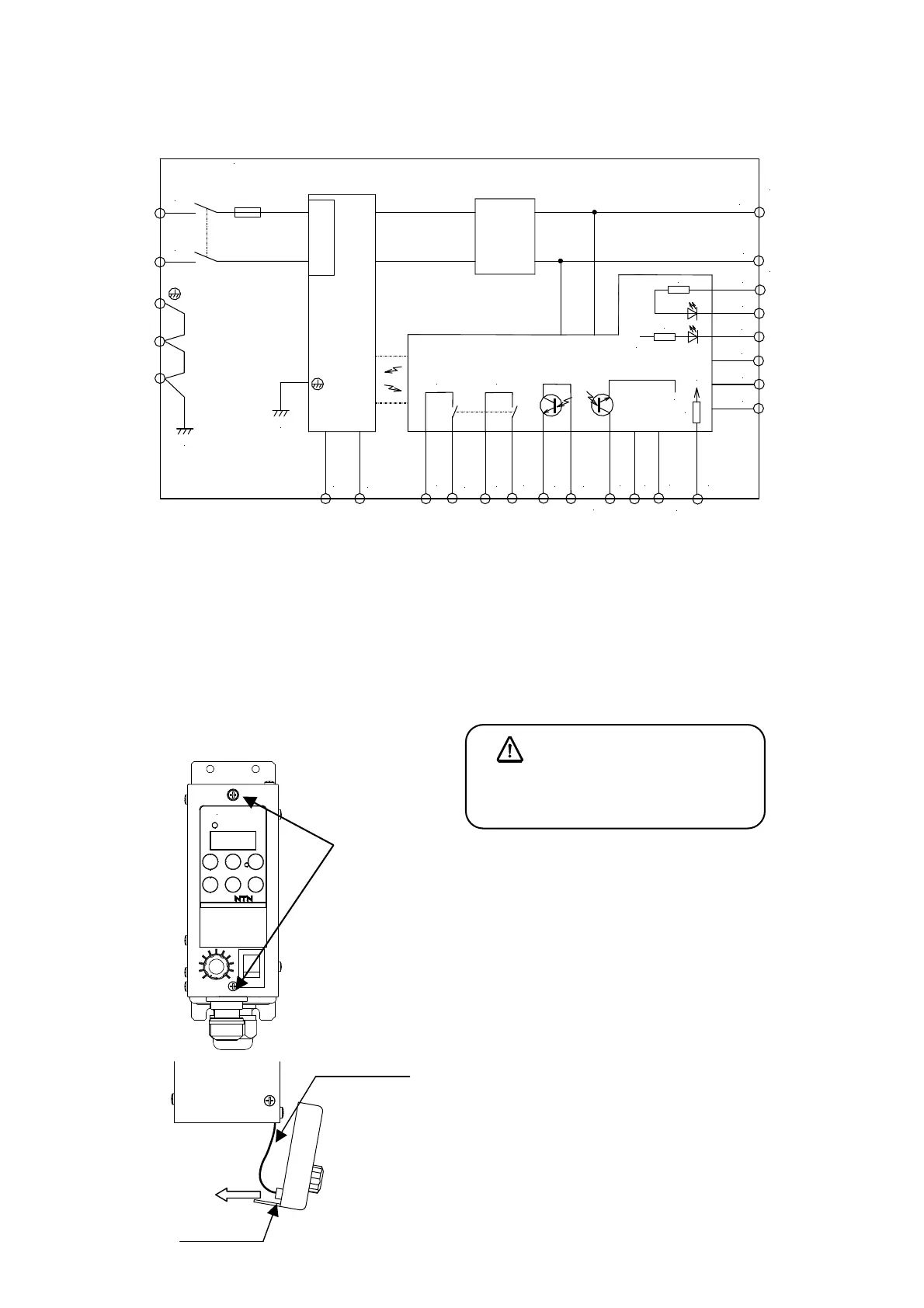
Controller block diagram(Refer to the previous page and the final page for wiring)
*1 The array of the terminal in the above figure is different in sequence order from the actual terminal array.
*2 0V of the input circuit and 24V of the input/output circuit are all common.
*3 The input circuit of IN1, IN2, B1 and B2, and the circuit configuration of the output circuit of P0, P1 and P2
are the same circuit configuration respectively.
(1) Remove the panel
①Loose two fixing M3-screws on operation panel and
remove operation panel. They are drop-out
protection types and if they are turned 3 to 4 times,
they will come off. If they are turned excessively,
they may drop out.
②Operation panel is connected to internal main circuit
board with cable. Pull out connector of operation
panel side, then remove operation panel.
Note) Wiring work while operation panel remains
connected, may load to the connector of main circuit
board side and result in loose connection. Be sure to
perform wiring work after cable is removed from
operation panel.
Danger
Do the wiring work after turning off the
main breaker without fail.
K-ECF25
JAPAN
①Loose
電源
電源
スイッチ
FUSE
3A(ECF25)
5A(ECH45)
出力
アース
直流電源
BOX
L
N
1
2
C1EM
C2
Y1C
Y1A
Relay
コントローラ K-ECF25(ECH45)
インバータ
回路
AL1
突入電流抑制回路
Relay
制御信号出力
(ねじ端子台)
BOX
}
制御回路
0V
+24V
IN2
IN1
+V
X1
(実際の端子配列とは順番が違います)
}
B1
B2
A1
P0
P1
P2
制御信号出力
(ばね式端子台)
+24V
3.3k
3.3k
10k
アナログ入力
(ばね式端子台)
制御信号入力
(ばね式端子台)
0V
負荷
}
}
サービス電源
(ばね式端子台)
CPU
Powe
Earth
Power
switch
Inrush current
restraining circuit
Inverter
circuit
DC
ower
Control circuit
Load
Output
Analog input
(Spring terminal board)
Control signal output
(Spring terminal board)
Control signal output
(Screw terminal board)
Service Power
(Spring terminal board)
*
2
Control signal input
(Spring terminal board)
*
3
Controller K-ECF25 (ECH45)
(Sequence order is different from the actual terminal array.)
Cable
Connector
②Pull out
connector
Operation panel