18
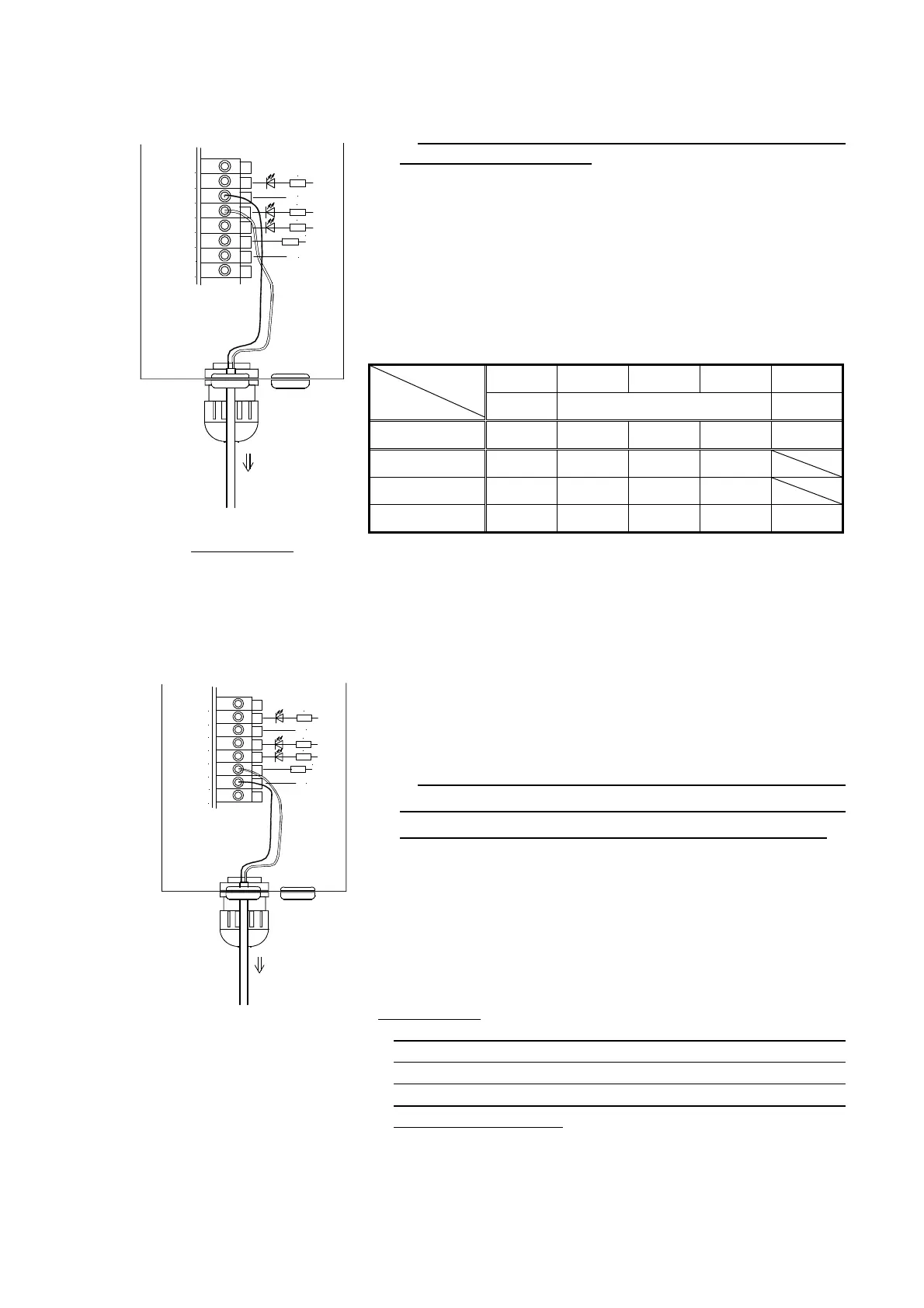
(6) Multi-speed function
(6) - 1. In case that memorized speed data is used
Control signal must be either NPN transistor output type or
no-voltage contact output type.
It is possible to drive at the speed data (frequency and voltage
value) memorized inside of the controller by using terminals B1 and B2.
Speed 1 is attained by short-circuiting the terminal B1 to 0V, speed 2
by short-circuiting the terminal B2 to 0V, seed 3 by short-circuiting both
terminals B1 and B2 to 0V, and in case of both terminals being open,
the speed is set by the panel (also refer to “Note on wiring” below).
The setting of each speed can be done by writing the data directly in
the function H12 to H17 or by transferring the present value at which
the machine is driven to the specified speed (Refer to P.35 and P.37).
Speed 0
Speed1
Speed 2 Speed 3 Analog
Panel Digital memory Outside
Function H11 0 0 0 0 1
Terminal B1 OFF ON OFF ON
Terminal B2 OFF OFF ON ON
Terminal A1 Invalid Invalid Invalid Invalid Valid
Note on wiring
The length of the cable connected to output lines such as B1, B2 and 0V shall be within 10m,
and be careful of the noise sufficiently.
(6) – 2. In case that the remote control is made by analog voltage
When the function H11 is set to 1, the output voltage can be
controlled directly from the outside by the analog voltage value. The
size of the output voltage is controlled by the analog voltage added
between terminals 0V-A1.
It can be used in stead of the speed control
knob.
The maximum voltage is 5Vdc. This terminal is connected
directly to the microcomputer chip (CPU) and if the excess voltage
is applied to it, it may break. Therefore be careful of it sufficiently.
The standard is that the output voltage is 0V for the terminal A1
voltage of 0.05V or less and AC200(100)V for 4.86V or more. The
output voltage changes by 1V when the input voltage changes by
about 22mV (in case of 100V, it changes by 1V for the change of
about 44mV). Input has ±5% error (individual difference). Please
confirm the set voltage on the actual equipment at setting.
Note on wiring
Analog signal line (A1,0V) treats a minute voltage. Therefore take
care for the wiring such as that the length shall be within 5m and the
shielded wire is used. The noise becomes the change of set value
directly and therefore when wiring is bad, the display and the output
voltage become unstable.
センサへ
茶
青
IN1
IN2
0V
B1
B2
A1
0V
24V
0V
0V
10k
3.3k
3.3k
3.3k
Blue
Brown
To control panel
制御盤へ
IN1
IN2
0V
B1
B2
A1
0V
24V
0V
0V
10k
茶
青
3.3k
3.3k
3.3k
To control panel
Brown
Blue