9
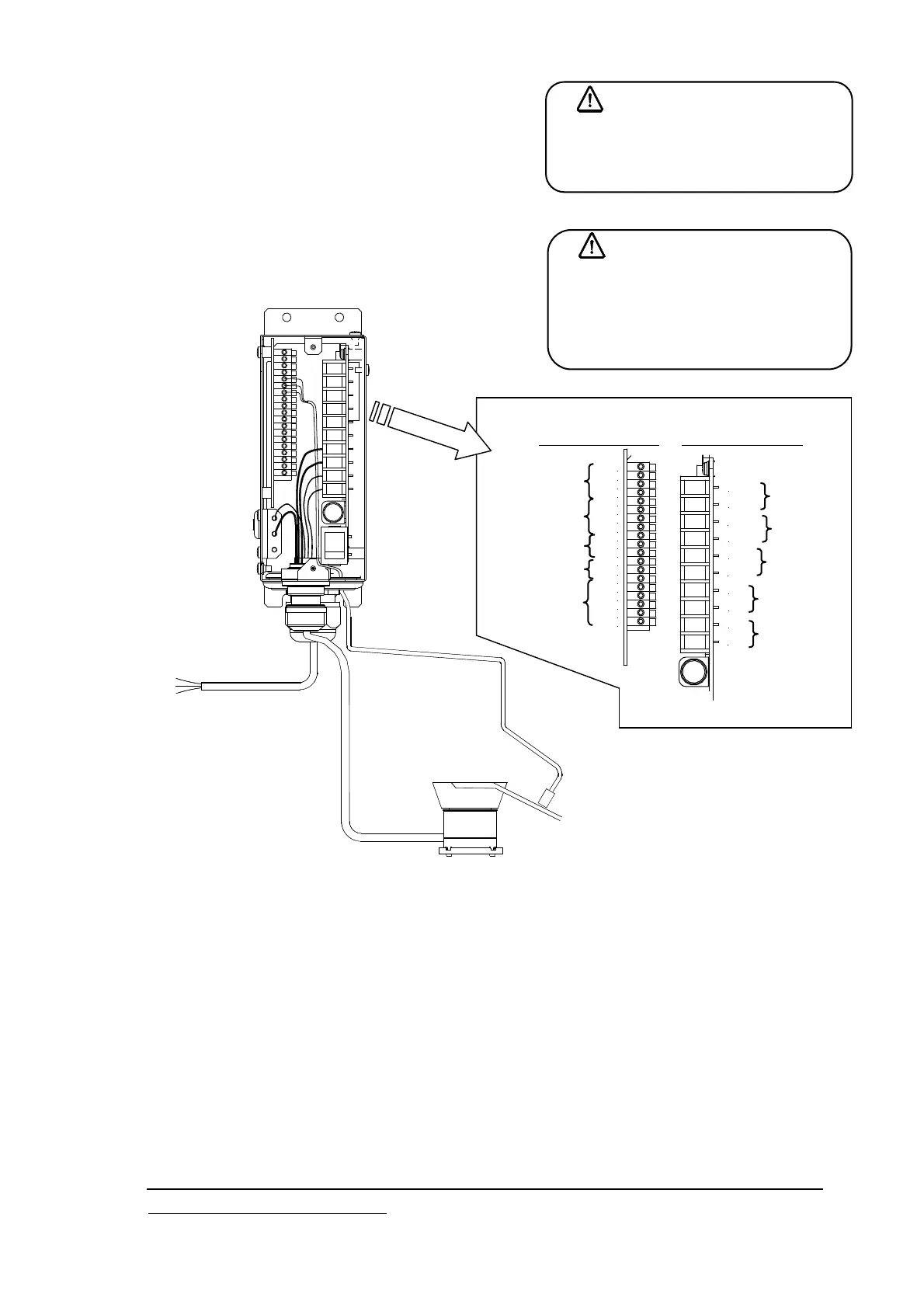
7. Connection of Input / Output
External connection diagram(Also refer to the block
diagram in the next page)
(Details of each wiring are described in the page shown in the
notes written below, therefore please refer to them.)
Caution
Please refer to the descriptions in caution for safety in P.2 to 4 and explanations for each item below for the
wiring method and cautions when wiring.
*1 Wiring of power supply P.11 Refer to paragraph “Connection to power supply”
*2 Wiring of load P.12 Refer to paragraph “Connection to load line”
*3 Wiring of external control signal P.13 to 14 Refer to paragraph “Wiring of external control input”
*4 Wiring of overflow sensor P.15 to 17 Refer to paragraph “Connection of sensor/solenoid valve”
*5 Receiving of drive signal P.19 Refer to paragraph “Wiring of drive instruction output”
*6 Others Multi-speed control P.18 Refer to paragraph “Multi-speed function”
Valve wiring P.16 to 17
Alarm/emergency signal P.19
※ Connecting method of input/output in the following pages is explained basically for ECF25, but the same
specification is also applied to ECH45.
Caution
Please select an appropriate type to the
kind and the size of the cable used and
responding to use conditions and the
environment.
Danger
Do the wiring work after cutting off the
main breaker without fail. It is likely to
get an electric shock.
[Array of terminal board]
24V
+V
X1
0V
24V
0V
IN1
IN2
0V
B1
B2
A1
0V
24V
P0
24V
P1
24V
P2
Y1A
Y1C
AL1
C1
EM
C2
2
1
N
L
*1
*2
*3
*4
*5
*6
*6
*6
Signal terminal board
Power terminal board
Pilot signal
Power
Load
Emergency
signal
Alarm signal
External control signal
Sensor signal
Speed switch signal
nalog signal
Valve control signal
パーツ
フィーダ
赤
白
緑
電源ケーブル
ワーク確認
センサ
負荷リード線
*1
*2
*4
It is connected to the single phase AC
power. Please connect it to
AC100-115V or AC200-230V according
to the voltage of the main vibration
body. The frequency is both for 50 and
60Hz. Connect green or green/ yellow
to the earth.
Parts feeder
*4 Work
confirmatio
sensor
Power supply cable
Load line
*2
Green
Re
d
White