15
(5) Connection of sensor/solenoid valve
Basic method to use sensor and solenoid valve
is explained as below.
1.Overflow control by sensor
①The work confirmation sensor that detects the overflow on the
chute is connected to terminals of 24V, 0V and IN1.
*1 The sensor that can be connected is limited to the one whose
current consumption is 50mA or less and the NPN transistor
output type that can be operated at the voltage of DC24V or
the non-voltage contact output type.
*2 Please connect +side of the sensor to IN1 and -side to 0V
when you use the two wire type DC sensor. Please use the
sensor of leakage current 1mA or less and residual voltage
3V or less. Turning off of the input signal may not be
detected according to the kind of sensor. In this case, please
connect the bleeder resistance to between terminals
24V-IN1 (tightened together with the sensor lead).
Bleeder resistance: 7~5.1kΩ, 1/2~1/4w
*3 Wiring of the non-voltage contact type is the same as that of
the DC two wire type sensor. Bleeder resistance is not
necessary.
②Please make the terminal IN1 open, and set the function H00 to 0
when you do not use the sensor. As the terminal IN1 is always
monitored, if the setting is mistaken, there is a possibility that
driving is not executed (The rightmost decimal point of the data
display portion turns on a light when there is a signal of logic that
instructs work existence in the sensor input) (Refer to the figure
below).
③The signal logic of the sensor (normally open/normally close)
can be changed by the function H00 (Refer to P.33).
Caution
Driving stops when the power supply (DC24V) for the
sensor is short-circuited (the display also is turned off).
Please be careful of the wiring work sufficiently.
About breeder resistance
When the pilot light of the sensor blinks
but
such a symptom as that the controlle
cannot capture the signal of the senso
comes out, insert the breeder resistance.
Normally the wiring is not required.
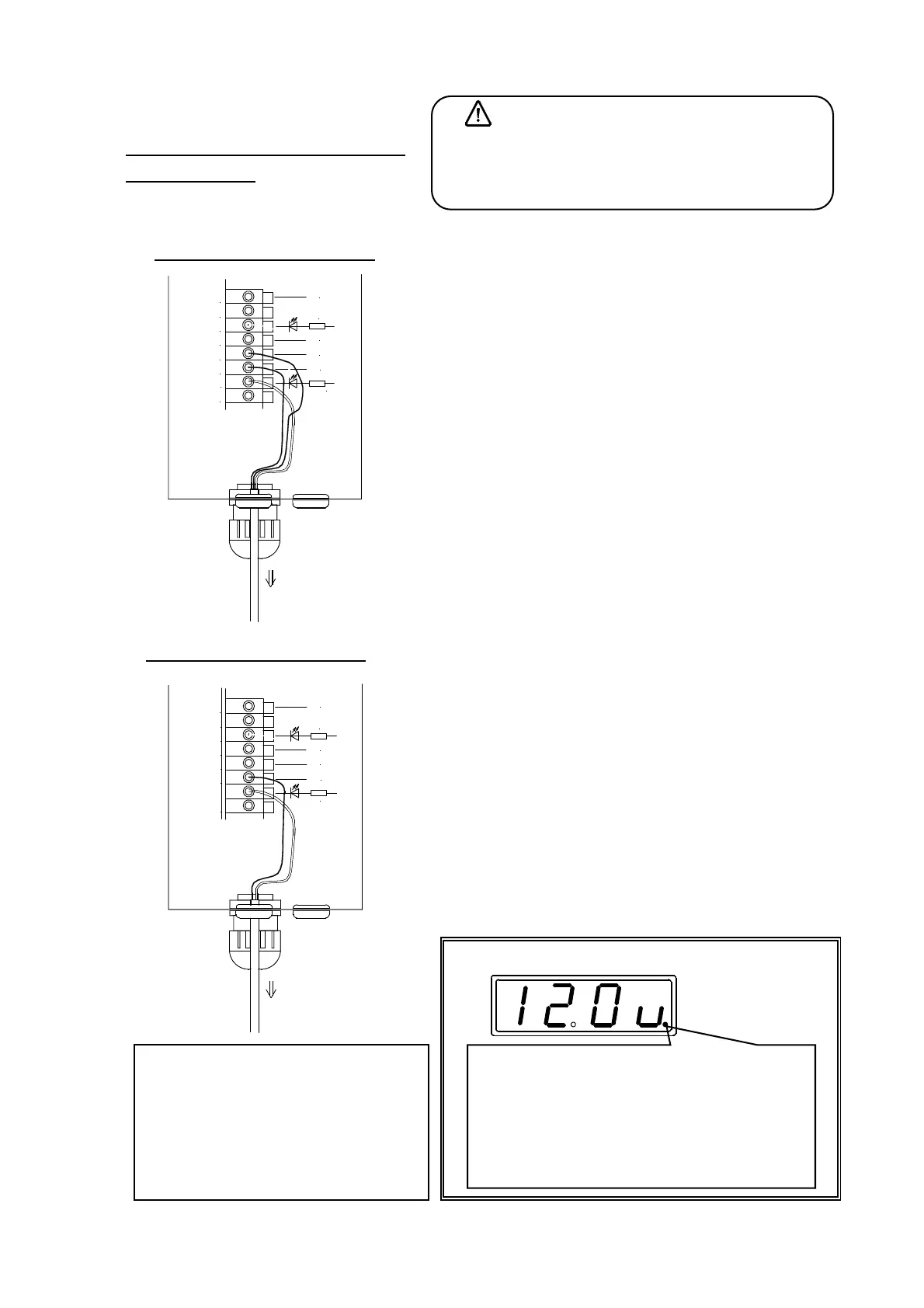
Connection of 2 wire type sensor
Connection of 3 wire type sensor
Display of sensor signal by LED(Also refer to P.36)
The decimal point lights when the signal of sensor 1
indicates the state of work existence. The state o
sensor 2 is expressed by the third digit from the righ
(white small circle
in the above figure). Only when the
use of the sensor is set, it is displayed. Please do no
mistake it for the decimal point.
センサへ
24V
+V
X1
0V
24V
0V
IN1
IN2
+24V
3.3k
0V
0V
+24V
3.3k
青
茶
黒
To sensor
Brown
Black
Blue
センサへ
24V
+V
X1
0V
24V
0V
IN1
IN2
+24V
3.3k
0V
0V
+24V
3.3k
茶
青
To sensor
Blue
Brown