14
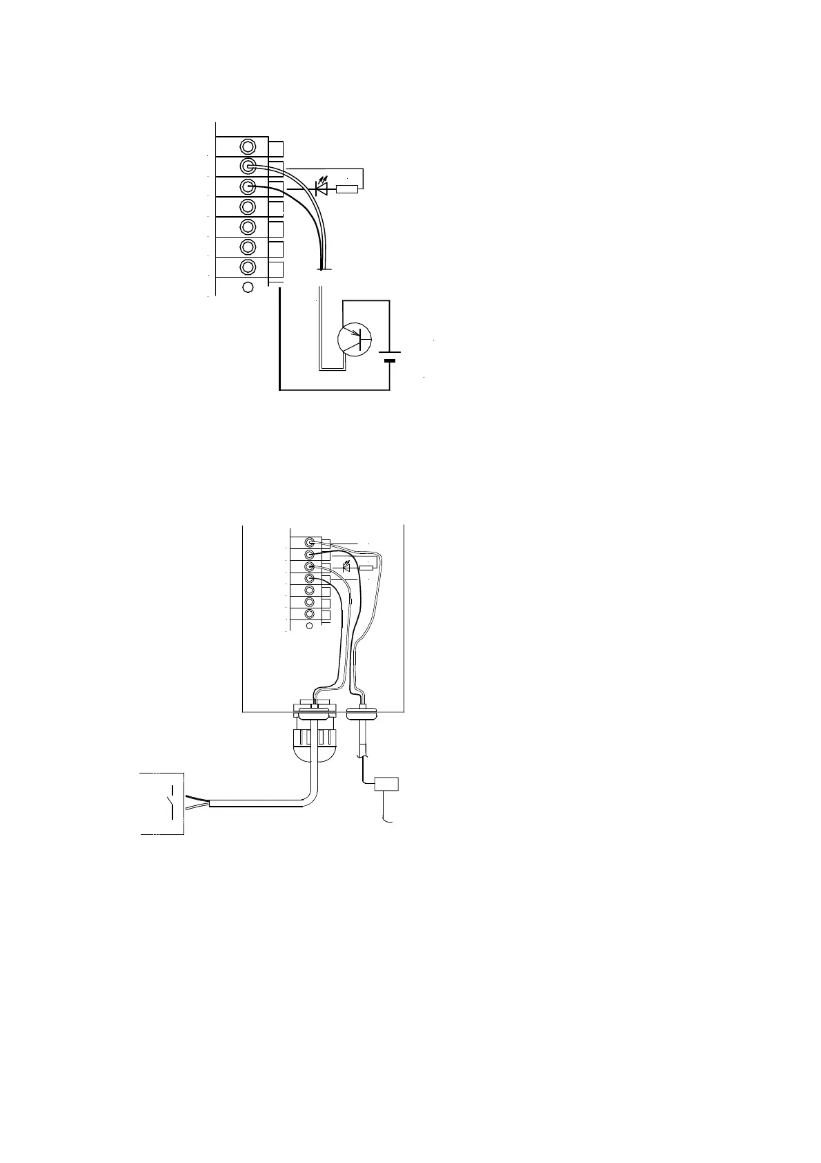
*1 Wiring method when controlling with PNP transistor output
For the electric wire size for wiring, refer to the boxed article in the middle of the previous page.
When controlling by the PNP transistor, please
connect the output (collector) side of the PNP
transistor to +V terminal, and the terminal X1 to
the common line (0V) side of the controlling
equipment. The current of about 7mA flows under
the control with 24V because internal resistance
of 3.3kΩ is connected.
Your 24V power supply is used in case of the
PNP control.
It is possible to control similarly even by the relay
contact instead of the transistor.
The selection of the logic of the driving or the
stop at the short-circuit can be selected by the
function J02.
*2 Wiring method when connecting to the hopper separately placed
①Connect the hopper separately placed to
the terminals of earth bar 1 and 2.
②Connect the level switch of the separately
placed hopper to between the terminals
24V-+V.
③Insert the pilot signal (Y1C, Y1A) of the
controller for bowl feeder into between
terminals X1-0V.
④Use data of function J02 by setting it as 1
(between terminals X1-0V [ON when
short-circuited]).
In the above-mentioned connection, the separately placed hopper drives only when the bowl feeder
is driving and also the level switch is ON (short-circuited between terminals 24V-+V). The current of
DC24V/7mA flows in the level switch.
*1 Please refer to the operation manual of the separately placed hopper.
*2 Please refer to the previous page for the terminal X1-0V (external control).
X1
0V
+V
24V
Your control circuit
制御用ケーブル
レベルスイッチを
24V-+V間に接続する
ボウルフィーダ
運転中信号
コントローラ等
24V
+V
X1
0V
24V
0V
IN1
IN2
+24V
3.3k
0V
Controller etc.
Bowl feeder’s pilot
signal
Cable for control
Connect
the level switch to
between 24V- +V
24V
+V
X1
0V
24V
0V
IN1
IN2
3.3k