17
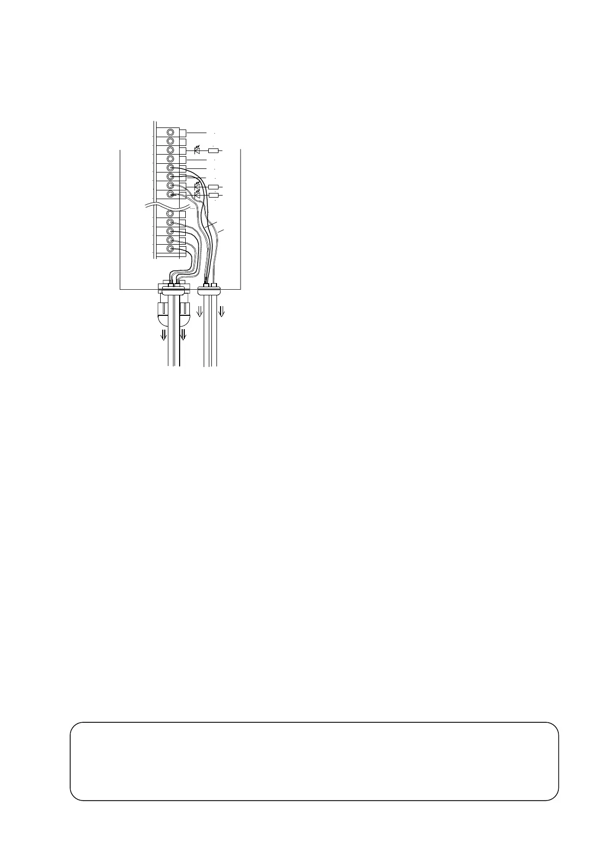
4. Two rows AND air overflow control by two sensors
(In case that overflow is controlled by air)
When discharging with two rows by the parts feeder, in case of
using the air for discharging the work due to overflowing, the
overflow control for each row with use of air becomes possible by
installing two sensors for overflow and setting the function H00 to 4
or 5.
The signal of sensor 1 is processed at set time of ON/OFF delay
timer 1, and output to the terminal P1, and the work is discharged
by the air at the time of full work. The signal of sensor 2 is
processed at set time of ON/OFF delay timer 2, and output to the
terminal P2, and the work is discharged by the air at the time of full
work. The parts feeder is stopped, and the air is turned off for the
case of both sensor 1 side and sensor side 2 being full.
Be careful that the total current consumption of the sensor and
the solenoid valve does not exceed the capacity (200mA) of
controller's service power supply. The terminal P0 can be used for
ON/OFF of supplementary air during driving while using the
terminals P1 and P2.
The configuration and the switching capacity of the drive circuit
of P1 and P2 terminals are the same as those of the terminal P0
(Refer to P.16).
Other notes for the connection are also the same as for the
terminal P0.
When the solenoid valve is not connected, it is possible to use it as two rows AND overflow control in the
paragraph 5 (1) below. In this case, although a logic reversing of each input becomes possible, because the
timer is added for each, it is necessary to set the time of timer for both 1 and 2 of ON/OFF Delay.
5. Other controls by sensor and solenoid valve
In addition to 1~4 explained above, the following controls are possible.
(1) To stop the parts feeder with the two rows AND overflow by using two sensors in case of discharging
two rows by the parts feeder. (In case that air is not used for the overflow control)
(2) In case that one row is discharged on the chute, overflow sensor is fitted respectively to chute inlet
and outlet, then when the work exists, the sensor at the chute inlet turns the parts feeder OFF, and
when the work does not exist, the sensor at the chute outlet turns the parts feeder ON.
(3) The overflow sensor on the chute outputs this sensor signal to the terminal P2 as well as controlling
the normal overflow (branching of signal).
(4) The overflow sensor controls the normal overflow and also outputs the jam signal to the terminal P2
when the work is not detected for a certain time. It can be used for jam air blow control of NTN
spring separate feeder.
※ As for the air overflow control (NTN internal nominal designation) explained on P.16~17, the behavio
becomes rather complicated. When you are already well aware of the content, it is possible to cover the wide
range control by using these functions. Please contact NTN for the detail or obtain separately the control
manual for confirmation.
バルブ2へ
24V
+V
X1
0V
24V
0V
IN1
IN2
+24V
0V
0V
+24V
赤
黒
24V
P1
24V
センサ1へ
茶
黒
青
P2
センサ2へ
バルブ1へ
P0
黒
3.3k
3.3k
3.3k
Black
Brow
Black
Red
Blue
Black
To sensor 2
To valve1
To sensor 1
To valve 2