16
2. Air blow control during driving
For the electric wire size for wiring, refer to the boxed article in the middle of P.13.
When connecting the solenoid valve for DC24V to between
24V-P0, the solenoid valve can be turned on during driving the
load (being linked with driving). Please use it when you want to
turn ON/OFF the air for tooling auxiliary in time along with parts
feeder's driving.
The solenoid valve that can be connected is for DC24V. Use the
one with the surge killer of 0.5W or less.
<Internal circuit of valve driving>
The transistor is turned on when
conditions are satisfied, and the terminals P0
and 0V are in continuity. Terminals P1 and l P2
are also similar.
Switching capacity: DC30V, up to 0.1A
Note
The length of the cable connected to the output lines of 24V,
P0, P1, P2 and 0V, etc. should be within 10m. Please wire the
device to which a noise suppression element is attached.
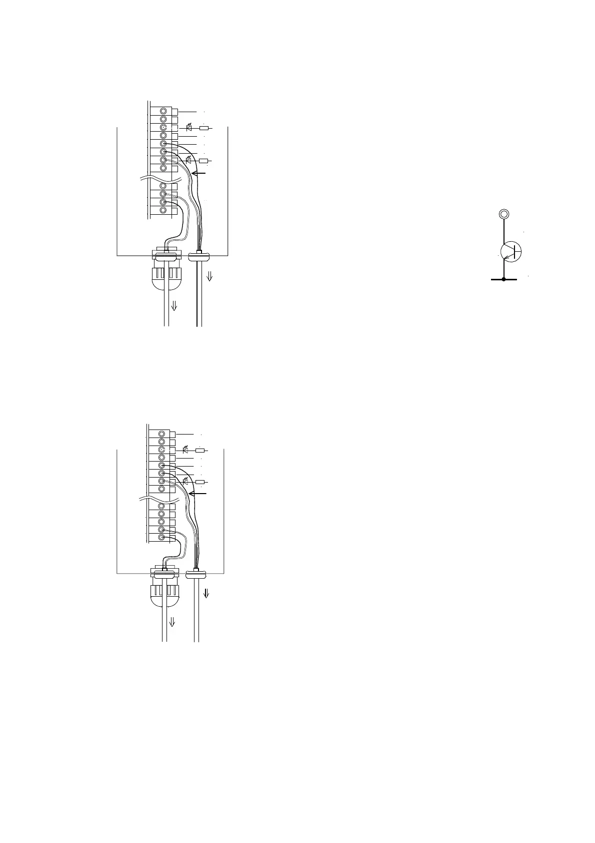
3. Air overflow control by sensor
When you control the overflow control with air by using the
sensor signal on the chute, please select 2 or 3 by the function
H00, and connect it as shown in the left figure. When 2 or 3 is
selected by function H00, parts feeder's control becomes only by
an external control with the use of the terminal X1 and after being
processed by the timer, the sensor signal drives the valve control
terminal P1. P1 becomes ON (OFF) in the state of full work and P1
becomes OFF (ON) in the state of work shortage. ON/OFF is
decided by selecting 2 or 3 (Refer to P.33. It is the same as a
logical reversing of the sensor signal). The terminal P1 doesn't
operate when driving stops.
Take care that the current consumption of the sensor and the
solenoid valve does not exceed the capacity of controller's service
power supply. The terminal P0 can be used for ON/OFF of the
supplementary air during driving while using the terminal P1.
The configuration and the switching capacity of the drive circuit
are the same as those of the terminal P0. Other notes for the
connection are also the same as for the terminal P0.
P0
0V
Tr
バルブへ
24V
+V
X1
0V
24V
0V
IN1
IN2
+24V
0V
0V
+24V
赤
黒
24V
P0
24V
センサへ
茶
黒
青
P1
3.3k
3.3k
To sensor
Blu
Brown
To valve
Black
Black
Red
バルブへ
24V
+V
X1
0V
24V
0V
IN1
IN2
+24V
3.3k
0V
0V
+24V
3.3k
赤
黒
24V
P0
24V
センサへ
茶
黒
青
Blu
Black
Brown
Red
To sensor
To valve
Black