25
(6) Speed (voltage) adjustment
①Please turn the speed adjustment knob gradually clockwise, and
set it to the position at which a necessary amplitude is obtained.
When an instruction of a proper position exists, please follow
the instruction. Usually it is used between scales 4-7 (6-7 for
full wave system and 4-5 for half wave system).
*1 Please do not use the scale of 9 or larger. The voltage stability
worsens when used.
*2 Please note that the parts feeder doesn't operate when the sensor
is confirming the work.
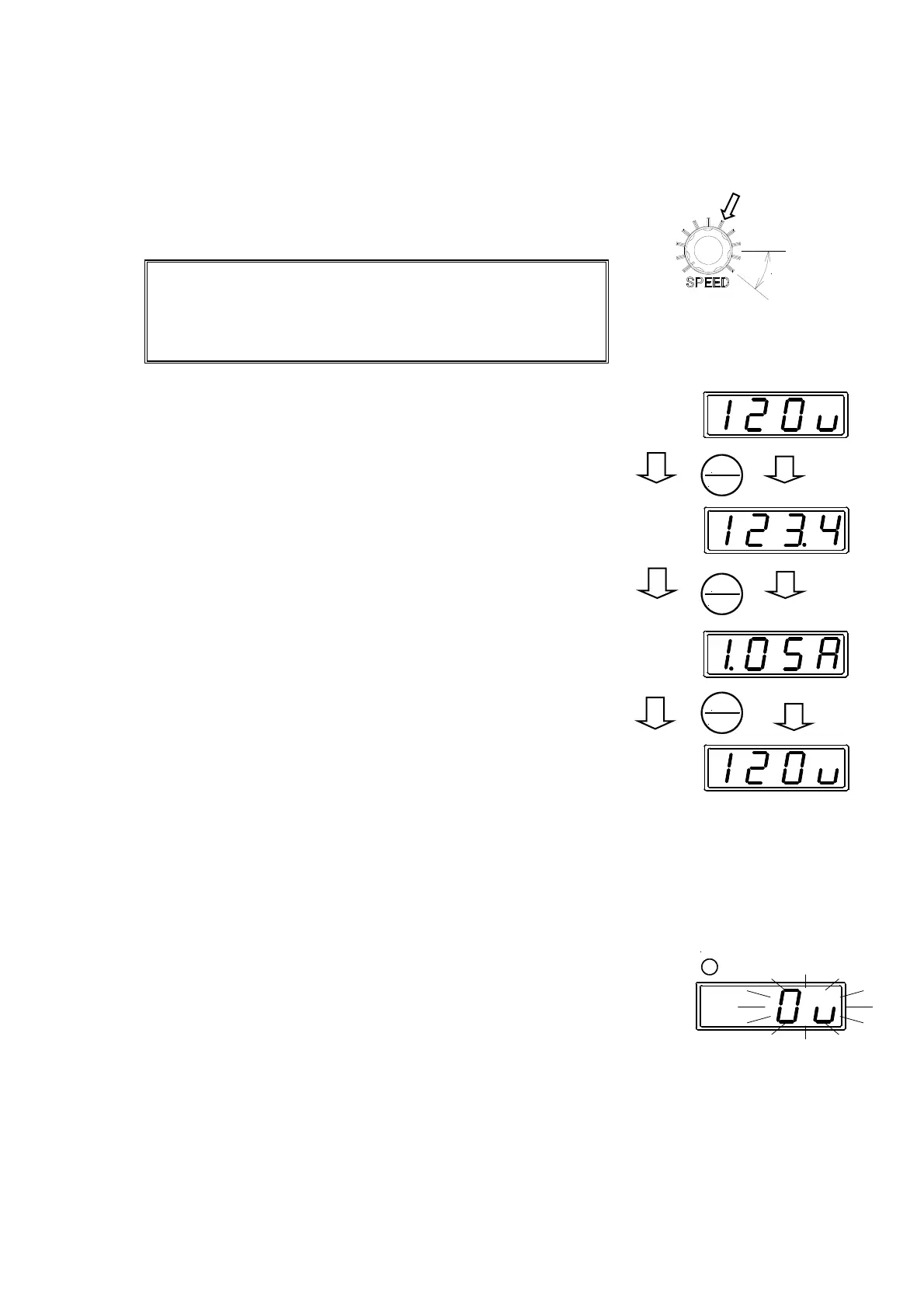
(7) Frequency monitor
①The set frequency can be monitored by pressing the data key. The
set frequency can be changed by pressing UP or DN key when the
frequency is being displayed.
②It becomes a current display if the data key is pressed again during
frequency being displayed, and it returns to the voltage display
when pressing again. It automatically returns to the voltage display
if the key operation is not done for 20 seconds or more.
(8) Current monitoring
① Present output current is displayed by pressing the data key
during the frequency is being displayed. It can be a guide to
know if there is any room in the operation state of load.
Please note that error is large in the region of very small
current (less than 0.2A for ECF25 and less than 0.5A for
ECH45).
② It returns to the voltage display when the data key is pressed
again while displaying the current. It automatically returns to the
voltage display if the key operation is not done for 20 seconds or
more.
(9) Stop
①Please cut the driving signal from the outside (Make it to the stop
side). Please press the STOP key when the selection of the
driving method is "Panel control."
The data display becomes blinking of "0", and the RUN pilot lamp
is turned off.
*Please note that the driving does not stop immediately even if
controller's power supply is turned off while driving.
*We recommend that the driving method is an external control
in a usual situation of use. Using the panel control is
convenient when manufacturing or adjusting. Please refer to
P.28 and 31 for the selection of the driving method.
Voltage display
(normal display)
Frequency display
Current display
void this
range
Set mark
DATA
ENTER
DATA
ENTER
DATA
ENTER
RUN
Voltage display
(normal display)