36
Panel lock
In order not to have the set value changed even if an operator touches the knob by mistake, it is
recommended to turn on the panel lock during the automatic operation. There are two kinds of panel locks,
an operation lock set by the function and a simple knob lock.
・ The operation lock can turn the function on and off by the function J00, and prohibits all the operations
and changes in data, excluding minimum necessary functions.
・ The knob lock is a function that locks the data simply, and locks only the data of the voltage value and
the frequency. Other operations and changes in data are possible. This lock is not a mechanical lock
but it is the one to prohibit the operation of changing data electrically.
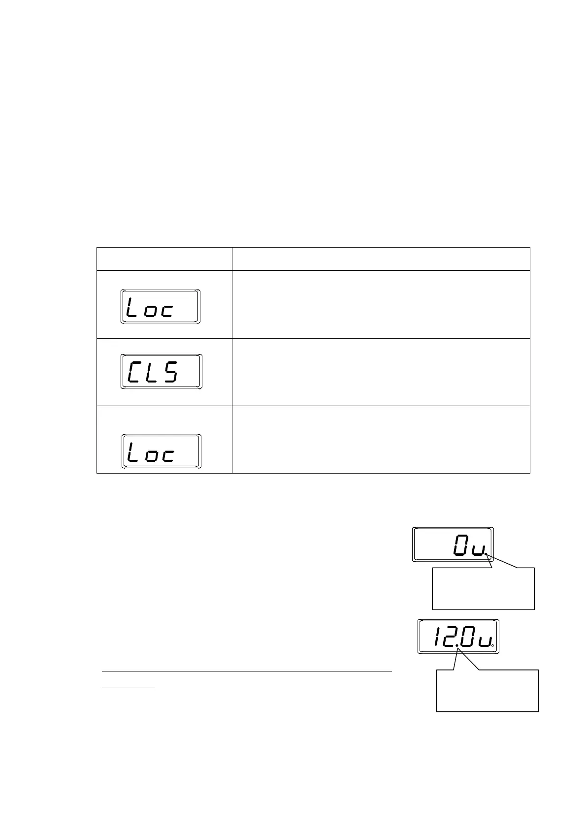
Operation of knob lock
Operation and display Description
Setting
A long pressing on the data key for three seconds or more on the normal
screen turns ON the knob lock. The characters of Loc blink for two seconds.
Such as the change in the data of the function is not locked. The operation
lock is given priority when the operation lock is set.
Release A long pressing on the data key for three seconds or more during the knob
lock turns the knob lock OFF (release). The characters of CLS blink for two
seconds.
When the operation lock is released, the knob lock is also released.
In case when a prohibited
operation is done
When the prohibited operation is done while locking, the characters of Loc
blink for two seconds, showing that the operation is prohibited. It returns to
the normal screen after blinking. The display blinks similarly when operated
while locking.
Notes related to LED display
The decimal point on the extreme right of 7seg LED displays the input state
of sensor 1 (IN1). Because the dot lights when the input of the sensor is in the
condition side of the drive stopping (stop of work supply), the signal state of the
sensor can be confirmed.
The second dot from the left of 7seg LED displays the input state of sensor 2
(IN2). The dot lights under the condition side of the drive stopping (stop of work
supply), and displays how the input condition of sensor 2 is going, same as
sensor 1.
*Please note that the second dot from the left used in displaying IN2 is not a
decimal point.
*When the driving is stopping with the sensor signal, “RUN” ramp
blinks.
Sensor 1 lights at the
stop side
Sensor 2 lights at the
stop side.