45
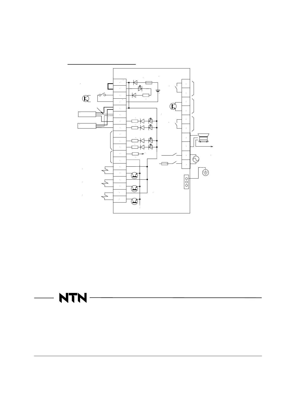
[Reference diagram of wiring]
The following diagram is a simplified diagram with focusing on the input-output terminals connected to the outside.
・This manual might be changed without notice for the function improvement etc.
Revised : July 1, 2013
Issued : Aug. 18, 2010
NTN
Technical Service Corporation
Product engineering section Precision equipment dept Iwata Division
1578 Higashi-Kaizuka, Iwata, Shizuoka 438-8510 Japan
PHONE
:
81-0538-37-8104
FAX
:
81-0538-37-8128
All rights reserved. ©NTN Technical Service Corporation 2013
*1 配線工事・各種調整等に際しては取扱説明書を必ず読んでください。間違えると故障・
事故の可能性があります。
*2 リモート端子を使用しない場合は、接点の代わりにジャンパ線を接続してください。
*3 24Vと0V端子はそれぞれ内部で全て接続されています。
*4 電流制限器:入力回路に流れる電流も含めた合計値が200mAに近付くと電圧降下を始めます。
緑/黄
AC100~115V
/200~230V
50/60Hz
アース
パーツフィーダ
N
ECF25/ECH45接続図
L
1
2
外部制御信号
ヒューズ ECF25:3A
ECH45:5A
+V
アースバー
アースバーへ
※アース線の色は緑
または黒の場合も
あります。
SOL(DC24V)
MAX 200mA
センサ1
青
茶
黒
センサ2
青
茶
黒
速度切替え
信号入力
アナログ入力
(速度指令)
MAX 5V
緑/黄
EM
C2
C1
AL1
Y1C
Y1A
CR1
CR2
異常信号出力
警報信号出力
運転中信号出力
コントローラ内部
24V
X1
0V
A1
B2
B1
IN2
IN1
P0
24V
0V
0V
0V
24V
P1
24V
P2
24V
SOL(DC24V)
SOL(DC24V)
ジャンパ線
接点orTr
0V
24V
3.3k
3.3k
3.3k
3.3k
3.3k
10k
CPUへ
*3
*2
*3
*4
24V
電源
ヒューズ
DC24V
ECF25/ECH45 connection diagram
Inside of controller
Driving signal output
Warning signal output
Abnormal signal output
Fuse ECF25: 3A
ECH45: 5A
Jumper wire
Earth bar
Sensor 2
Speed switching
Signal input
nalog input
(Speed instruction)
Brown
Blue
Black
Brown
Black
Blue
External control signal
Contact point or Tr
Green
/Yellow
Parts feeder
To earth
*Color of earth wire
is green or black
Earth
Green/Yellow
Sensor 1
Power
Fuse
*1 Read the operation manual in doing wiring construction and other various adjustments.
Error may cause failure and accident.
*2 When you do not use a remote terminal, connect a jumper wire instead of contact.
*3 Terminals 24V and 0V are all connected in the inside.
*4 Current limiter: When total figure including current in input circuit comes close to 200mA, voltage starts to drop.