6
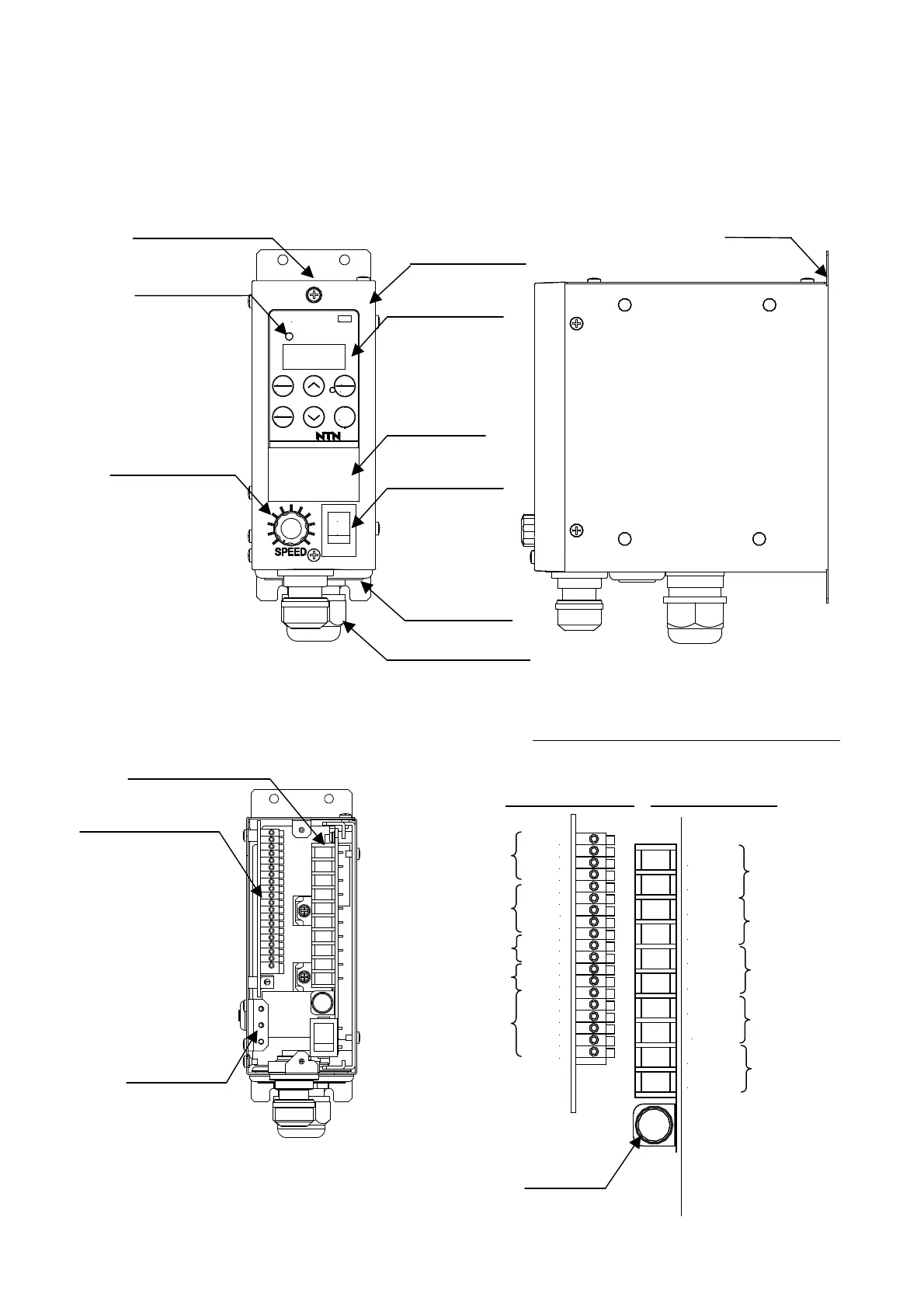
4. Appearance and Names of Portions
The following diagram is explained about K-ECF25. But the layout of parts is same with K-ECH45.
(1) Appearance diagram(Please refer to P.44 for dimensions)
(2) Terminal board(the panel is open)
Terminal board layout(Magnified diagram)
Terminal names are printed on the board.
Signal terminal board Power terminal board
Signal terminal board
Power terminal board
Earth bar
K-ECF25
V.F. CONTROLLER
RUN
JAPAN
AC100-115/200-230V 50/60Hz 2A
FUNC
RESET
DATA
ENTER
STOP
JOG
RUN
l
0
RoHS
Speed control knob
Operation panel
Warning seal
Power switch
Rubber bush
Cable ground
Production No. (Ser.№)
Data display
Pilot lamp
Fixing leg
Pilot signal
Alarm signal
Emergency signal
Output
Power supply
Fuse
Y1A
Y1C
AL1
C1
EM
C2
2
1
N
L
24V
+V
X1
0V
24V
0V
IN1
IN2
0V
B1
B2
A1
0V
24V
P0
24V
P1
24V
P2
External control input
Sensor input
Speed switch input
Analog input
Valve control output
ECF25/3A
ECH45/5A