38
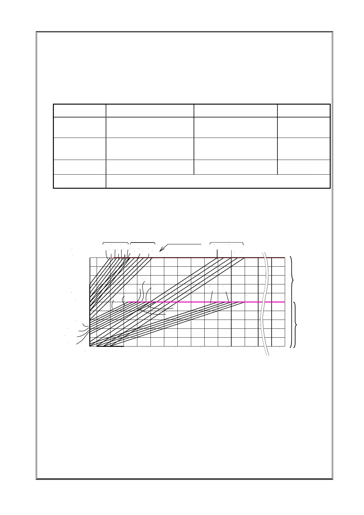
F/V curve
To protect the magnet for driving the part feeder, the frequency-voltage recession curve is installed. Please
switch to the F/V curve to be used according to the main body and the drive system used. The F/V curve can be
switched by the function J04. The line of the set F/V curve is the upper boundary value for a set voltage in each
frequency. It is independent of the overload protection function by the current rating, and the output voltage is
limited when it reaches the upper boundary value of the F/V curve even if it is not an overloading state.
Selection of F/V curve
F-V curve
*1 Number of F/V curves installed in this controller is 18 in total, but usually select the one from the three of F/H/C.
When you use № 0-17, examine the characteristic of the load current and set it after investigation if it leads to
overloading.
*2 Please do the overload protection of the magnet by the setting function of the current rating. However, when it is not
possible to protect it by the setting function of the current rating of such as minute current load, the protection by the
F/V curve is the alternate.
*3 When the parts feeder made by other company is used or a curve other than for F/H/C is selected, there is the case
that protection by the F / V curve is impossible. Please note that NTN is not responsible for the trouble that
originates from these circumstances.
*4 When the power supply voltage is 100V, the upper limit value is also 100V.
Curves for 100V and 200V automatically
change according to the power supply voltage.
Function J04 Full wave driving main body Half wave driving main body
High frequency main
body
F
(F-V curve №3)
S05~S20, L20, MD10~MD20
K10~K20
*2
, N25~N40
*2
[S20]
*1
[N25・1]
*1
Refer to P.28 and 31 also.
―
H
(F-V curve №9)
―
K20, N32~N40
*2
, G50・1
*2
SV01~SV06, SV1~SV3
S30, V01~V12
*2
, MD30
―
C
(F-V curve №15)
―
―
HF10, HF14
HS05, HS07
0~17
[Special use]
*1
*1 The main body inside of [ ] is a special specification. Please consult NTN when setting it.
*2 For the main body of 100V full wave drive of K20, the 100V main body of N25 and V01~V08, and the main
body of N32~N40 and G50/1, K-ECH45 is an applicable controller.
出力電圧[V]
0
80
100
出力周波数 [F]
120
160 200
全波系
[V]
200
4
7
10
11
12
9
8 6
5
半波系
2
3 1
0
14
17
16
15
13
高周波系
240
280
[Hz]
13
14
15
16
17
12
2,8
1,7
0,6
30
40
5,11
12
5,11
4,10
3,9
500
F-V
カーブ№
3,9
4,10
Curve fo
200V
Curve fo
100V
Half wave
system
Full wave
system
F-V
Curve №
High-frequency
system
Output frequenc
[F]
Output voltage [V]