13
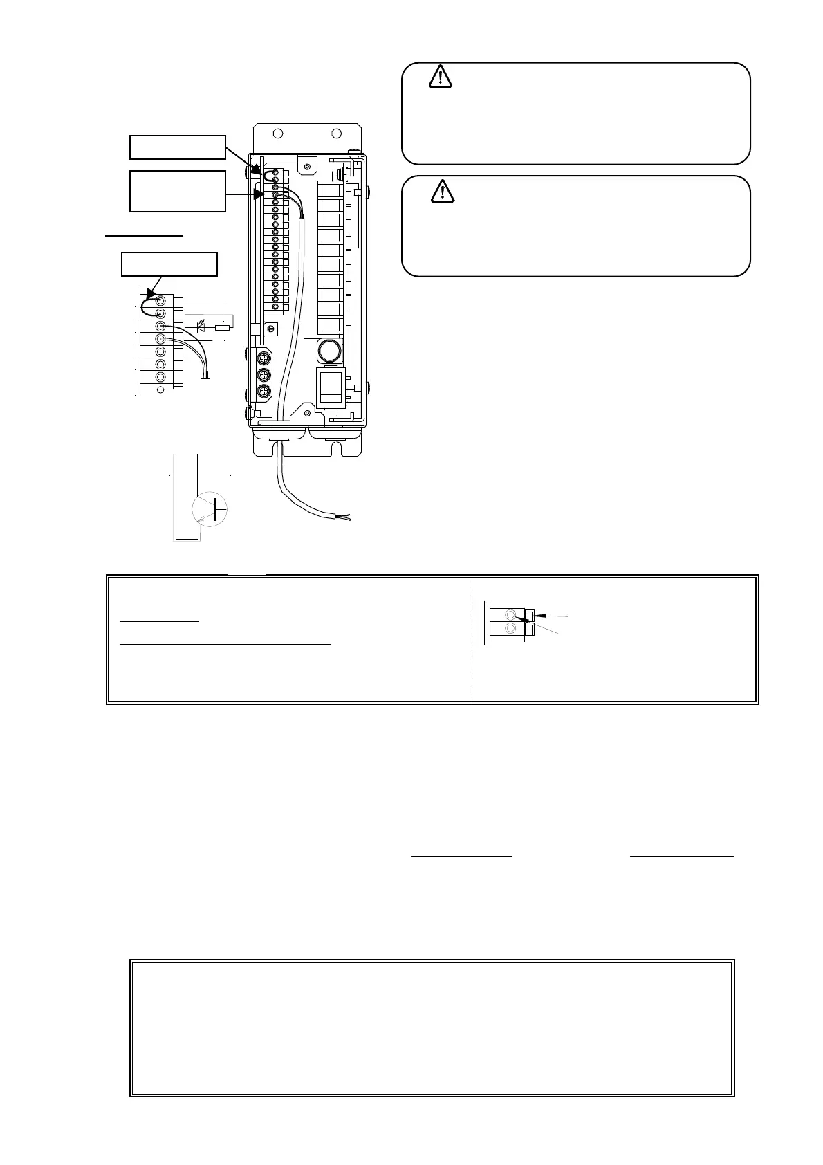
(4) Wiring of external control input
Wiring method to control parts feeder’s ON/OFF from
outside when the function is a standard setting, is
explained.
① The short circuit between terminals 24V-+V is
confirmed. When there is neither jumper wire nor
control wire etc. for the short circuit, short circuit shall
be made.
② The jumper wire between terminals of X1 and 0V is
removed, and the relay contact (or NPN transistor) is
connected between these terminals. Use the IN input
when the ON/OFF delay timer is used.
Cables used to control should be prepared in your
company.
Size of wire used for terminal board (spring type) for signal
For strand wire
: 0.14~1.0mm
2
Length of stripping: 10mm
For use of sleeve type crimping terminal
: 0.25~0.34mm
2
Example of sleeve type crimping terminal:
AI0.25-12BU [Phoenix contact]: 0.25 mm
2
When function №. JO2 is set as 1 (standard), followings are resulted.
・ With short-circuited state between X1-0V, parts feeder is driven (for NPN transistor output, it is Lo level)
・ With open state between X1-0V, parts feeder is stopped (for NPN transistor output, it is High level)
When the logic is reversed (JO2 is set as 0) by the function, it is driven with open state. Please refer to P.31
for the setting of the function JO2.
Please refer to the next page when controlling by the PNP transistor
output or using it for the hopper control.
Note 1 The current of DC24V 7mA flows between terminals X1-0V. Please be careful of the noise
enough because it is a minute electric current.
Note 2 The cable length of signal input line (24V, +V, X1, 0V) should be within 10m. Adopt a twist wiring if it is
possible.
In case of no external control used
When the external control terminal is not used, make function J02 setting as "1" and have the
external control input terminal short-circuited (at two positions of 24V-+V and X1-0V). The controller
drives continuously. Even if the setting of J02 is made "0" and the external control input terminal is
opened, it becomes a continuous driving.
Caution
24V, X1 and 0V terminals have polarity. Please be
careful of wiring enough. In addition, please never
connect it to AC power.
Caution
Parts feeder's ON/OFF control must use the
external control input terminal. ON/OFF control by
the power supply is impossible.
X1
0V
NPN
トランジスタ
abc
Remove
umper
wire
Jumper wire
NPN
Transistor
Your control circuit
24V
+V
X1
0V
24V
0V
IN1
IN2
+24V
3.3k
0V
Jumper wire
Magnified view
Signal
wire
Wiring to signal terminal board
溝
電線穴
While inserting the minus driver into the groove and pushing
the electric wire deep, insert the wire into the electric wire hole.
Release the driver, then the electric wire is fixed.
Groove
Electric wire hole