LPC5411x All information provided in this document is subject to legal disclaimers. © NXP Semiconductors N.V. 2018. All rights reserved.
Product data sheet Rev. 2.1 — 9 May 2018 87 of 105
NXP Semiconductors
LPC5411x
32-bit ARM Cortex-M4/M0+ microcontroller
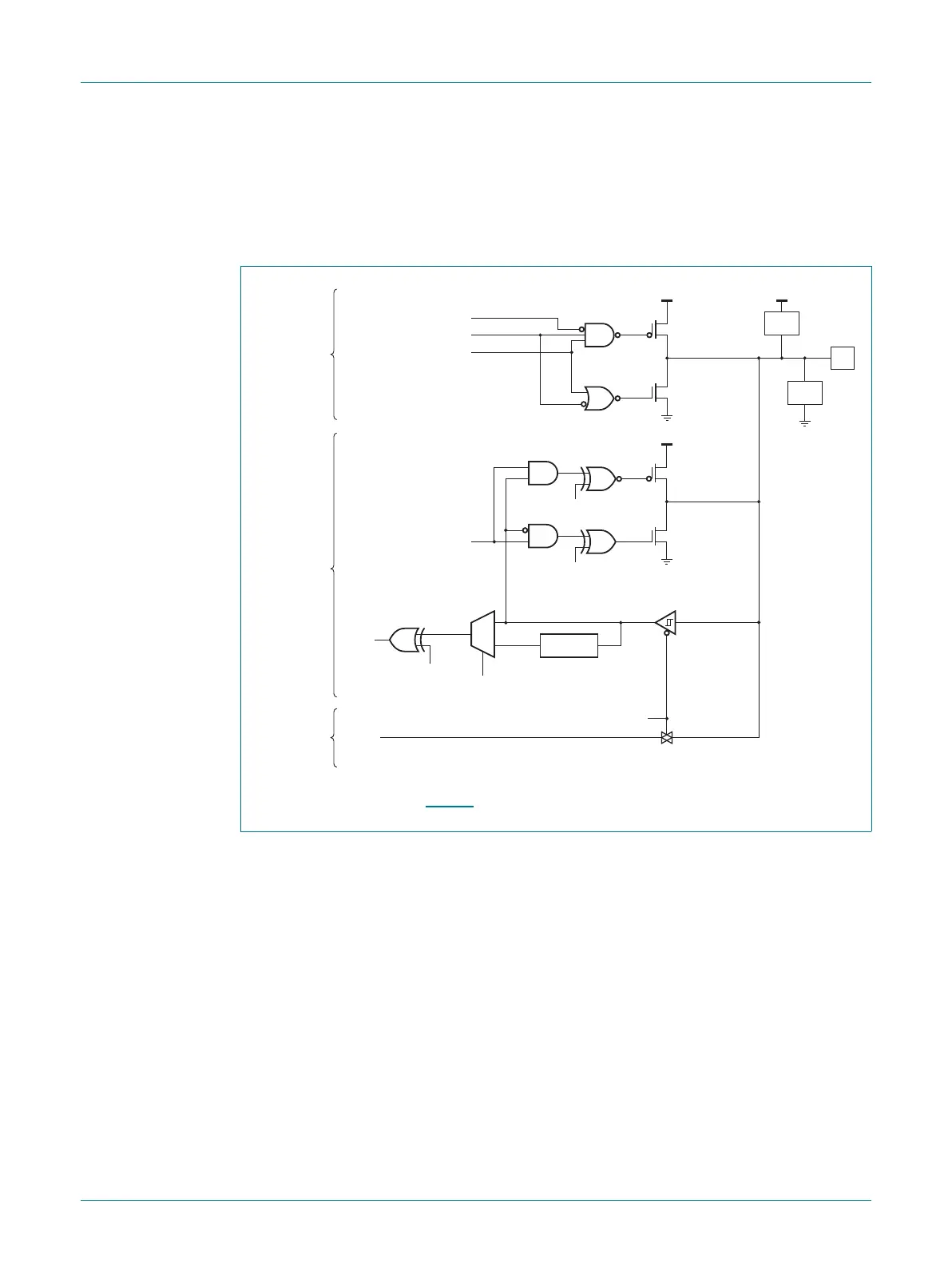
• Digital input: Repeater mode enabled/disabled.
• Z mode; High impedance (no cross-bar currents for floating inputs).
The default configuration for standard I/O pins is Z mode. The weak MOS devices provide
a drive capability equivalent to pull-up and pull-down resistors.
The glitch filter rejects pulses of typical 12 ns width.
Fig 31. Standard I/O and RESET pin configuration
aaa-017273
pin configured
as digital output
open-drain enable
output enable
data output
pin configured
as digital input
pin configured
as analog input
digital
input
analog
input
enable
input invert
enable
filter
glitch filter
PIN
ESD
ESD
strong
pull-up
V
DD
V
DD
V
DD
strong
pull-down
pull-down enable
pull-up enable
weak
pull-up
repeater
mode enable
enable
analog input
weak
pull-down

 Loading...


