9
H.264 4/8/16-channel Networkable DVRs
SECTION 2: INSTALLING YOUR SYSTEM
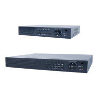
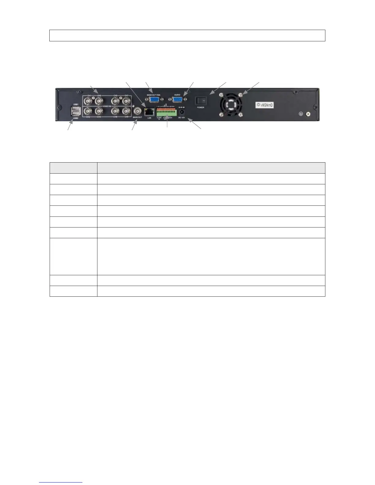
DVR9008N Back Panel (8 channel)
CH1 - CH8
Video In
Audio
LAN
Main Out (BNC)
Main Out (VGA)
Power Fan Exhaust
Alarm In/Out,
RS485 Terminals
USB Power DC 12V
Connector Usage
CH1 .. CH8 Video channel input connectors.
LAN RJ-45 connector for Ethernet LAN.
MAIN OUT VGA Video out VGA interface connector.
AUDIO DB9 connector for input adapter for audio channels 1 .. 8 (associated with video channel inputs 1 .. 8, respectively).
POWER Main power switch.
POWER DC 12V 12 Vdc adapter power input connector
Alarm In/Out,
RS485 Terminals
Alarms in 1 .. 4 terminations: For connecting to external sensor device, each alarm has one input pin. Connect positive (+)
output pins of the alarm device to the inputs (Alarm In) on the DVR. Connect ground (-) output pins of the alarm device to the DVR
Ground slots (G). Multiple devices can be connected to one ground slot.
Alarms out terminations: NO, COM pins for alarm out normally open (N.O.)
RS-485 terminations: A, B pins for connecting to RS-485 network (PTZ camera control)
MAIN OUT BNC Video out BNC interface connector.
USB1, USB2 Use these USB ports to connect a mouse, or a backup device such as a ash drive or DVD recorder.