45850101TH Rev.1
2-41
2. TROUBLESHOOTING PROCEDURES
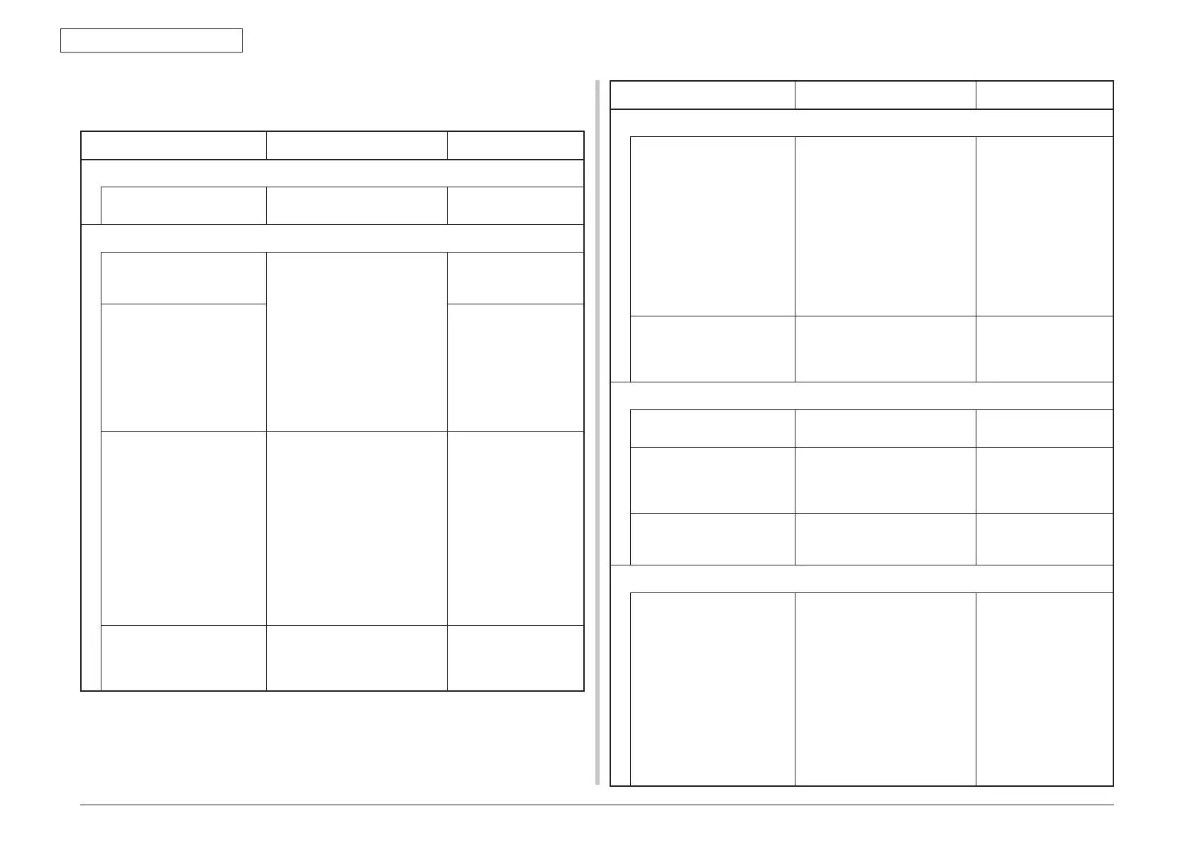
2.5.5.(1) LCD Display Trouble
(1-1) LCD displays nothing
Check item Check work
Actions to be taken
at NG
(1-1-1) Checking fuse
Fuse on Scanner board
(6SU)
Check whether F2 or F6 has
blown.
Replace F2 or F6 or
Scanner board (6SU).
(1-1-2) Checking connections
Connection between low-
voltage power supply unit
and Scanner board (6SU)
Make sure the low-voltage
power supply unit is connected
to the POWER_IN connector
on the Scanner board (6SU)
properly.
Check whether the cable
connector is half-connected
or tilted, or whether wires are
broken.
Check whether there is any
fault in the cable assembly, e.g.,
missing wires.
Connect the cable
properly.
Cable assembly connecting
low-voltage power supply
unit to Scanner board (6SU)
Replace the cable with
a good cable.
Connection between
Scanner board (6SU) and
operation panel
Make sure the 22-pin FFC is
connected to the 7 INCHIF
connector on the Scanner
board (6SU) properly.
Make sure the 22-pin FFC is
connected to the SUIF
connector
on Panel board (TP1)
properly.
Check whether the cable
connector is half-connected or
tilted.
Connect the cable
properly.
FFC connecting Scanner
board (6SU) to Panel board
(TP1)
Check for broken wires using a
tester.
Check visually whether the
sheath peels.
Replace the cable with
a good cable.
Check item Check work
Actions to be taken
at NG
(1-1-2) Checking connections
Connection between
Scanner board (6SU) and
CU/PU board
Make sure the 50-pin FFC
is connected to the CD2_CUIF
connector on the Scanner
board (6SU)
properly.
Make sure the 50-pin FFC
is connected to the CD2_CUIF
connector on the CU/PU board
(6CU) properly.
Check whether the cable
connector is half-connected or
tilted.
Connect the cable
properly.
FFC connecting Scanner
board (6SU) to CU/PU
board (6CU)
Check for broken wires using a
tester.
Check visually whether the
sheath peels.
Replace the cable with
a good cable
(1-1-3) Checking power supplies
AC power supplied to the
printer
Check the supplied voltage
from the AC power source.
Supply AC power.
3.3VS and 5V power
supplied to Scanner board
(6SU)
Check the 3.3VS power at 1 pin
and 5V power at 3, 4 pin of the
POWER_IN connector on the
Scanner board (6SU).
Replace the low
voltage power supply
or CU/PU board (6CU)
5V and 3.3VS power
supplied to Panel board
(TP1)
Check the power at pin of the
CN1 connector on the Panel
board (TP1).
Replace the Scanner
board (6SU).
(1-1-4) Checking for short circuit of power supply
3.3VS, 5V and 24V power
supplied to Scanner board
(6SU)
Check for a short circuit using
the POWER connector on the
Scanner board (6SU).
1pin: 3.3VS
3,4pin: 5V
7,8p i n : 24V
2,5,6,9,10pin 0V
If there is a short circuit, locate
it.
Disconnect the cables from the
Scanner board (6SU) one by
one to
locate the short circuit.
Replace the short-
circuited component.