45850101TH Rev.1
4-22
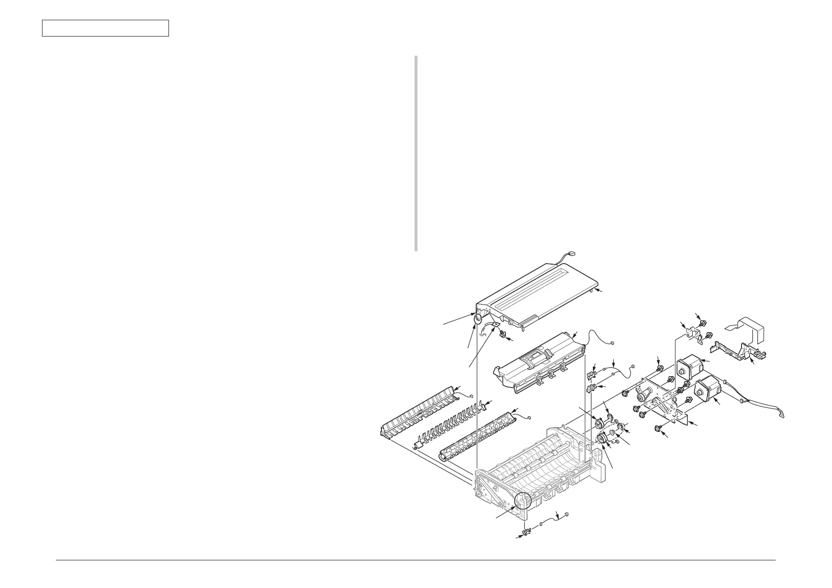
4.2.10.8 Guide-Retard / Cover-Assy-Top-ADF /
Motor / CONN Coard / Clutch / Photo-sensor
(1) Remove all cables from Guide-Cable-ADF
①
and remove it.
(2) Remove two screws(silver)
②
and remove the plate-clutch
③
.
(3) Remove the Cluch Assy.
(4) Remove a E-type retaining ring
④
and remove a bearing
⑤
and clutch
⑥
from the
Cluch A ss y.
(5) Remove a E-type retaining ring
⑦
and remove a clutch
⑧
.
(6) Remove the five screws (silver, No:42920406)
⑨
and remove the plate-motor
⑩
.
(7) Remove the four screws (silver, No:42920406)
⑪
and remove the two motors
⑫.
(8) Remove the two photo-sensors
⑬
and each of connectors of the CONN coard
⑭
.
㉒
②×2
③
⑤
⑥
⑦
⑧
⑨
×5
①
⑩
⑪
×4
⑫
⑬
⑬
⑭
⑮
⑱
⑰
④
⑬
⑯
⑲
⑳
Cluch Assy
Portion B
Portion A
Cover-Top(ADF-Sub)
(assembled to left side of
⑮
)
Stopper-Arm(ADF)
Ⓐ
Ⓐ
(9) Open the Cover-Assy-Top-ADF
⑮
. And, remove a screw (black:
42932710)
⑯
to detach Stopper-Arm(ADF). Next, Bend the portion
A with bending the Cover-Top(ADF-Sub) which is assembled to
left side of
⑮
to outside, and unlatch the post at the portion A of
the Cover-Assy-Top-ADF
⑮
. Subsequently, unlatch the post of
the other side of the portion A at the Cover-Assy-Top-ADF
⑮
,
and remove the Cover-Assy-Top-ADF
⑮
with passing the cables
though the shaft hole.
(10) Disconnect a cable of the Guide-Retard-A
⑰
, and bend around
the post at the portion B. Subsequently, unlatch the post of the
other side of the portion B at the Guide-Retard-A
⑰
, and remove
the Guide-Retard-A
⑰
with passing the cables though the shaft
hole.
(11) Remove the Guide-Assy-D
⑱
with disconnecting the cable.
(12) Remove the Guide-Separater-Revese
⑲
.
(13) Remove the Guide-Assy-C
⑳
with disconnecting the cable.
(14) Remove the photo-sensor
, cable
.