10-003591-01EN [Q7780031], Rev. 4, January 2020
Inspection 43
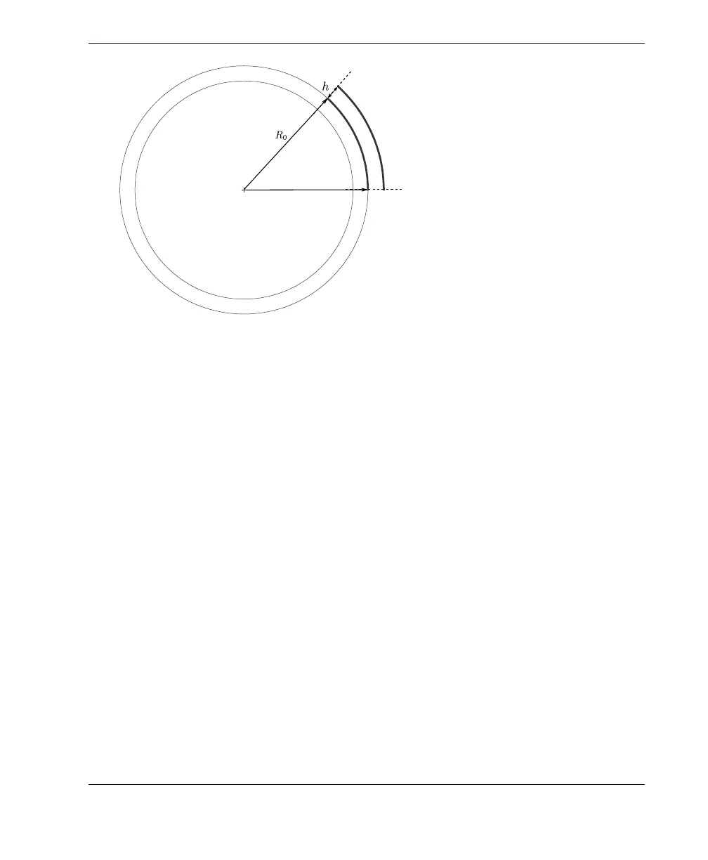
Figure 4-5 Variables for calculating probe beam width on the surface
(1)
Defect length correction (only along index axis)
Table 4 on page 44 provides correction factors (multiplication factors) that must be
applied to the measured defect length from inspection data along the index axis. The
table provides multiplication factors for a range of defect depths in typical inspection
applications.
For example, if a defect is measured to be 10 mm long along the index axis, 6 mm
below the surface on a 114 mm (4.5 in.) pipe, the multiplication factor is 0.77 and the
true defect length = 10 mm × 0.77 = 7.7 mm.
For inspection applications that fall outside the range of the table, the true defect
length can be calculated as shown in “Calculating True Defect Length” on page 77.
A = Active aperture length
B = Beam coverage width on the surface
h = Water column height (9 mm for SFA1-
FLEXO and SFA1-AUTO wedge series, and
11 mm for SFA1-SMALL wedge series)
R
o
= Outside radius
B
R
o
A
R
o
h+()
--------------------=