10-003591-01EN [Q7780031], Rev. 4, January 2020
List of Figures 79
List of Figures
Figure i-1 Labels location for scanner ................................................................................. 1
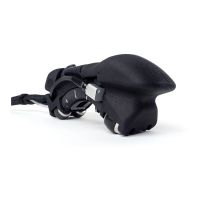
Figure i-2 FlexoFORM scanner .......................................................................................... 17
Figure 1-1 Case contents ...................................................................................................... 19
Figure 1-2 Scanner components ......................................................................................... 20
Figure 1-3 Mini-Wheel encoder standard hardware kit ................................................. 21
Figure 2-1 Selecting Plate in the Specimen Type field .................................................... 24
Figure 2-2 Symmetrical scan pattern for a pipe elbow inspection of 360° ................... 25
Figure 2-3 Installing the probe and wedge ....................................................................... 27
Figure 2-4 Scanner connections example .......................................................................... 28
Figure 3-1 Attachment point for lanyard .......................................................................... 30
Figure 3-2 Extrados — maximum outer elbow curve length ......................................... 31
Figure 3-3 Example Scan Start and Scan End setting in the OmniScan ........................ 32
Figure 3-4 Example index Resolution setting in the OmniScan .................................... 32
Figure 3-5 Marking the zero position (left) and scan (right) lines on an elbow ........... 34
Figure 3-6 Drawing the scan lines on an elbow ............................................................... 35
Figure 4-1 An example S-scan display free of bubbles ................................................... 38
Figure 4-2 Alignment marks ............................................................................................... 39
Figure 4-3 Scan pattern for a pipe elbow .......................................................................... 40
Figure 4-4 Probe element marks on the wedge ................................................................ 41
Figure 4-5 Variables for calculating probe beam width on the surface ........................ 43
Figure 5-1 Changing a wheel .............................................................................................. 48
Figure 5-2 Changing the encoder ....................................................................................... 50
Figure 5-3 Changing the foam gasket ................................................................................ 51
Figure 5-4 Changing the probe’s o-ring seal on the wedge ............................................ 52
Figure 5-5 Changing the o-ring seal for the water connection ....................................... 52
Figure 5-6 Changing the tube (shown disassembled) ..................................................... 53
Figure 5-7 Disassembly steps for changing the cable sleeve .......................................... 55
Figure 6-1 LEMO connector pinout diagram (5 pin to 16 pin) ...................................... 61
Figure 6-2 Scanner dimensions ........................................................................................... 62
Figure 6-3 SFA1-SMALL wedge clearances ...................................................................... 63