54
c
a
d
b
5
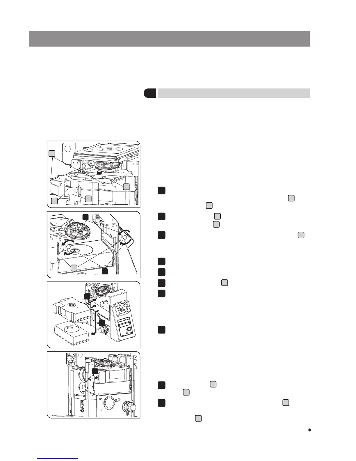
Mounting to Microscope Deck
4
5
3
6
7
IX3-RFACA, IX3-RFACS, IX3-CAS or IX3-RSPC can be mounted to the
microscope deck area. This section describes the procedure using IX3-
RFACA as an example, but the same procedure applies to other units.
} If the camera is attached to the left side port of the microscope, the
unit may interfere with the camera while mounting the unit. In such
a case, remove the camera before mounting the unit.
} If you use the stopper screw for the analyzer slider IX3-AN, attach
the stopper screw to the microscope first before attaching the fluo-
rescence illuminator or the fluorescence mirror turret to the micro-
scope decks. (page 43)
When the cable cover is in use, remove the cable cover on the back
side of the microscope. Turn the cable cover fixing knobs
a
, and
remove the cover
b
.
Remove the dust tray
d
placed on the left side of the microscope.
Turn the fixing knobs
c
(2 pcs.) and remove the dust tray.
By using the provided Allen screwdriver, loosen the fixing screws
e
(2
pcs.) of the deck where the fluorescence mirror turret is to be mounted
until the fixing screws slightly come out from the screw holes.
If the dummy box is attached to be deck, remove the dummy box.
Insert the fluorescence mirror turret.
Tighten the fixing screws
e
with the provided Allen screwdriver.
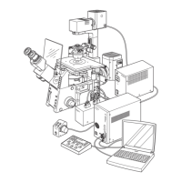
After installation of the fluorescence illuminator, connect the interface
cable U-IFCBL100 to the mirror turret.
} For the installation of the fluorescence illuminator, refer to the sepa-
rate instruction manual entitled "Refrected Fluorescence System".
Connect the opposite side of the interface cable U-IFCBL100 to the
IX3-CBM.
} Do not dispose of the cover and dummy box and keep them in a
safe place.
} When you want to remove the fluorescent mirror unit, be sure to
remove the reflected fluorescent illuminator first.
Attach the dust tray
d
to the microscope and tighten the fixing
knobs
c
(2 pcs.)
When the cable cover is in use, attach the cable cover
b
to the
back side of the microscope, and fix the one with the cable cover
fixing knobs
a
.
1
2
3
4
5
6
7
8
9
10
e