102
LD or LD NOT, to form ‘logic blocks’ that are combined by the right-hand in-
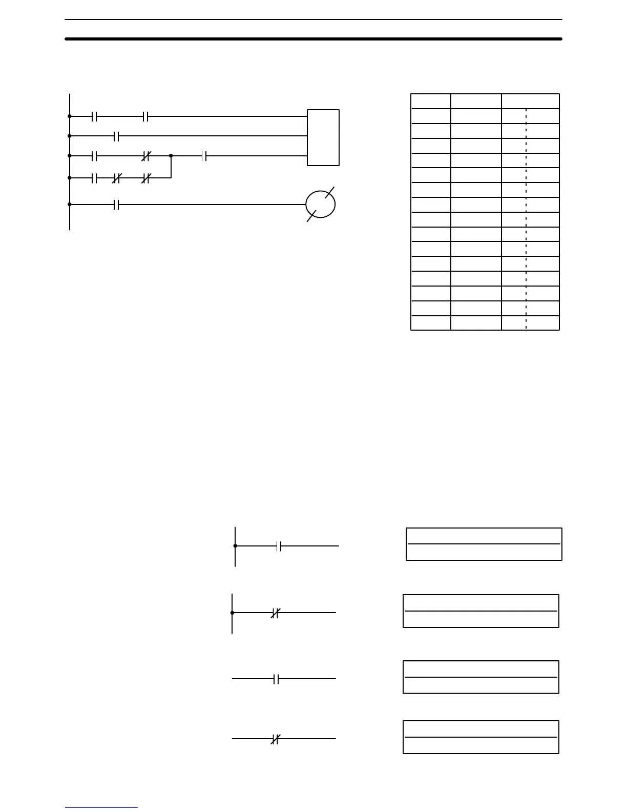
struction. An example of this for SFT(10) is shown below.
I
P
R
SFT(10)
HR 00
HR 00
Address Instruction Data
00000 LD 00000
00001 AND 00001
00002 LD 00002
00003 LD 00100
00004 AND NOT 00200
00005 LD 01001
00006 AND NOT 01002
00007 AND NOT LR 6300
00008 OR LD --
00009 AND 22500
00010 SFT(10) --
HR 00
HR 00
00011 LD HR 0015
00012 OUT NOT 00500
00100 00200
00500
01001 01002 LR 6300
22500
00002
HR 0015
00000 00001
When you have finished coding the program, make sure you have placed
END(01) at the last address.
5-6 Ladder Diagram Instructions
Ladder Diagram instructions include Ladder instructions and Logic Block in-
structions. Ladder instructions correspond to the conditions on the ladder
diagram. Logic block instructions are used to relate more complex parts of
the diagram that cannot be programmed with Ladder instructions alone.
5-6-1 LOAD, LOAD NOT, AND, AND NOT, OR, and OR NOT
B: Bit
IR, SR, AR, HR, TC, LR, TR
Ladder Symbols Operand Data Areas
LOAD – LD
B
B: Bit
IR, SR, AR, HR, TC, LR
LOAD NOT – LD NOT
B
B: Bit
IR, SR, AR, HR, TC, LR
AND – AND
B
B: Bit
IR, SR, AR, HR, TC, LR
AND NOT – AND NOT
B
END(01)
Ladder Diagram Instructions Section 5-6