23
If the content of bits 12 through 15 is B, an error has occurred in a Remote
I/O Master or Slave Unit, and the content of bits 08 through 11 will indicate
the unit number, either 0 or 1, of the Master involved. In this case, bits 04 to
06 contain the unit number of the Slave Rack involved.
If the content of bits 12 through 15 is a number from 0 to 31, an error has
occurred in an Optical I/O Unit. The number is the unit number of the Optical
I/O Unit involved, and bit 04 will be ON if the Unit is assigned leftmost word
bits (08 through 15), and OFF if it is assigned rightmost word bits (00 through
07).
3-4-2 Link System Flags and Control Bits
Use of the following SR bits depends on the configuration of any Link Sys-
tems to which your PC belongs. These flags and control bits are used when
Link Units, such as PC Link Units, SYSMAC LINK Units, Remote I/O Units,
SYSMAC NET Link Units, or Host Link Units, are mounted to the PC Racks
or to the CPU. For additional information, consult the System Manual for the
particular Units involved.
The following bits can be employed as work bits when the PC does not be-
long to the Link System associated with them.
Host Link Systems
Both Error flags and Restart bits are provided for Host Link Systems. Error
flags turn ON to indicate errors in Host Link Units. Restart bits are turned ON
and then OFF to restart a Host Link Unit. SR bits used with Host Link Sys-
tems are summarized in the following table. Rack-mounting Host Link Unit
Restart bits are not effective for the Multilevel Rack-mounting Host Link
Units. Refer to the Host Link System Manual for details.
Bit Flag
25206 Rack-mounting Host Link Unit Level 1 Error Flag
25207 Rack-mounting Host Link Unit Level 1 Restart Bit
25208 CPU-mounting Host Link Unit Error Flag
25209 CPU-mounting Host Link Unit Restart Bit
25213 Rack-mounting Host Link Unit Level 0 Restart Bit
25311 Rack-mounting Host Link Unit Level 0 Error Flag
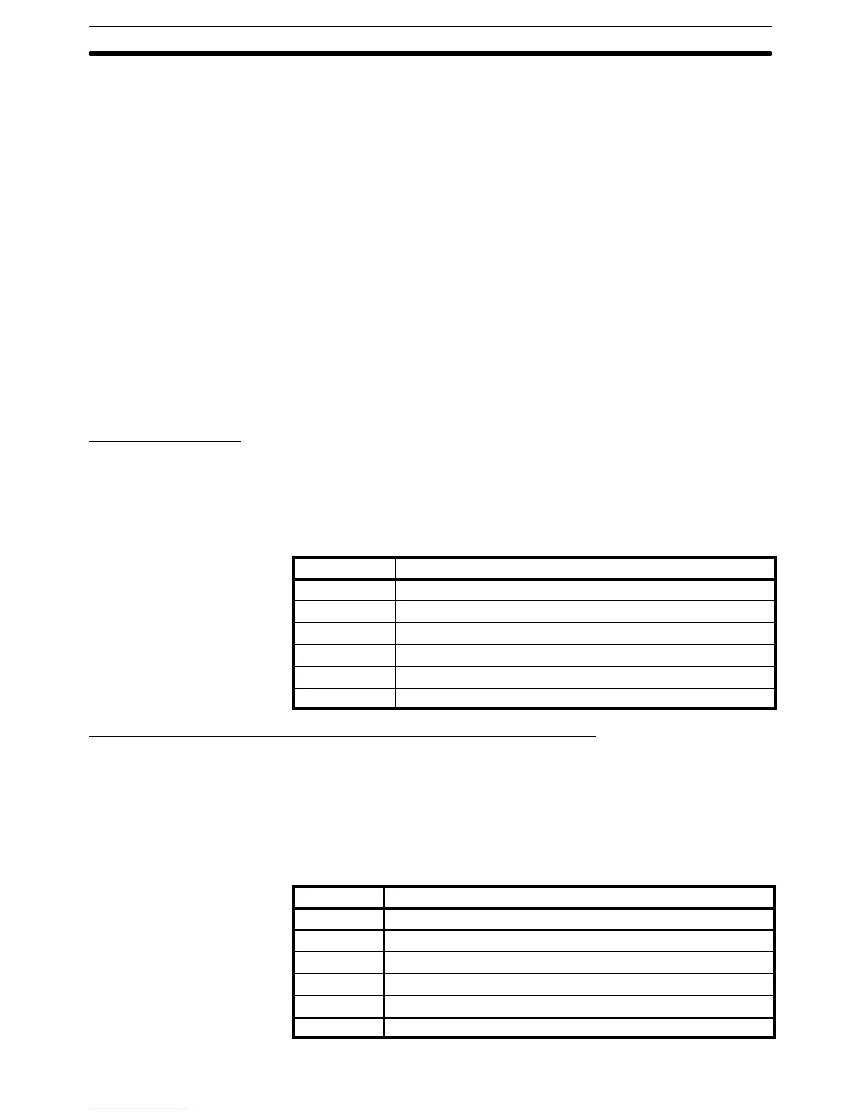
SYSMAC NET Link and SYSMAC LINK Systems (CPU11-E only)
SR 25200 turns ON to indicate an error has occurred in level 0, while using
SEND(90) or RECV(98) to transfer data in either a SYSMAC NET Link or
SYSMAC LINK System. SR 25203 indicates an error has occurred in level 1.
Turning ON SR 25201 enables SEND(90) and RECV(98) in level 0 in these
Systems. Turning ON SR 25204 enables SEND(90) and RECV(98) in level 1.
SR 25202 turns ON when a data link is active in operating level 0 of either of
these Systems and SR 25205 turns ON with a data link is active in operating
level 1. These flags and corresponding SR bits are shown below.
Bit Flag
25200 Operating Level 0 SEND(90)/RECV(98) Error Flag
25201 Operating Level 0 SEND(90)/RECV(98) Enable Flag
25202 Operating Level 0 Data Link Operating Flag
25203 Operating Level 1 SEND(90)/RECV(98) Error Flag
25204 Operating Level 1 SEND(90)/RECV(98) Enable Flag
25205 Operating Level 1 Data Link Operating Flag
SR Area Section 3-4