24
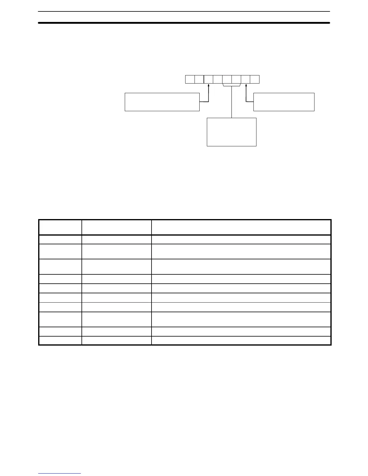
SR 236 contains the SYSMAC NET Link Loop Status Flags. Bits 00 through
07 are the Loop Status Flags for operating level 0, and bits 08 through 15 are
the Flags for operating level 1. The bit functions are shown below.
111 1
Level 0: 07 06 05 04 03 02 01 00
Level 1: 15 14 13 12 11 10 09 08
Central Power Supply Unit:
0: Power supply connected.
1: Power supply not connected.
Transmission status:
0: Reception possible
1: Reception not possible
Loop status:
11: Normal loop
10: Lower back loop
01: Upper back loop
00: Loop error
When SEND(90) or RECV(98) is used in a SYSMAC LINK System, a com-
pletion code is output to SR 23700 through SR 23707 for level 0, or SR
23708 through SR 23715 for level 0, to indicate whether or not the data
transfer was completed successfully and to indicate the nature of the error
when communications are not completed successfully. These error codes are
as follows.
SYSMAC LINK Systems
Completion
code
Name Meaning
00 Normal end Data transfer was completed successfully.
01 Parameter error SEND(90)/RECV(98) instruction operands are not within specified
ranges.
02 Transmission impossible The System was reset during execution of the instruction or the
destination node is not in the System.
03 Destination not in System The destination node is not in the System.
04 Busy error The destination node is busy and cannot receive the transfer.
05 Response timeout A response was not received within the time limit.
06 Response error An error response was received from the destination node.
07 Communications controller
error
An error occurred in the communications controller.
08 Setting error The node address was set incorrectly.
09 CPU error A CPU error occurred in the PC of the destination node.
SYSMAC NET Link Loop
Status Output
Communications
Completion Code
SR Area Section 3-4