25
SYSMAC NET Link Systems
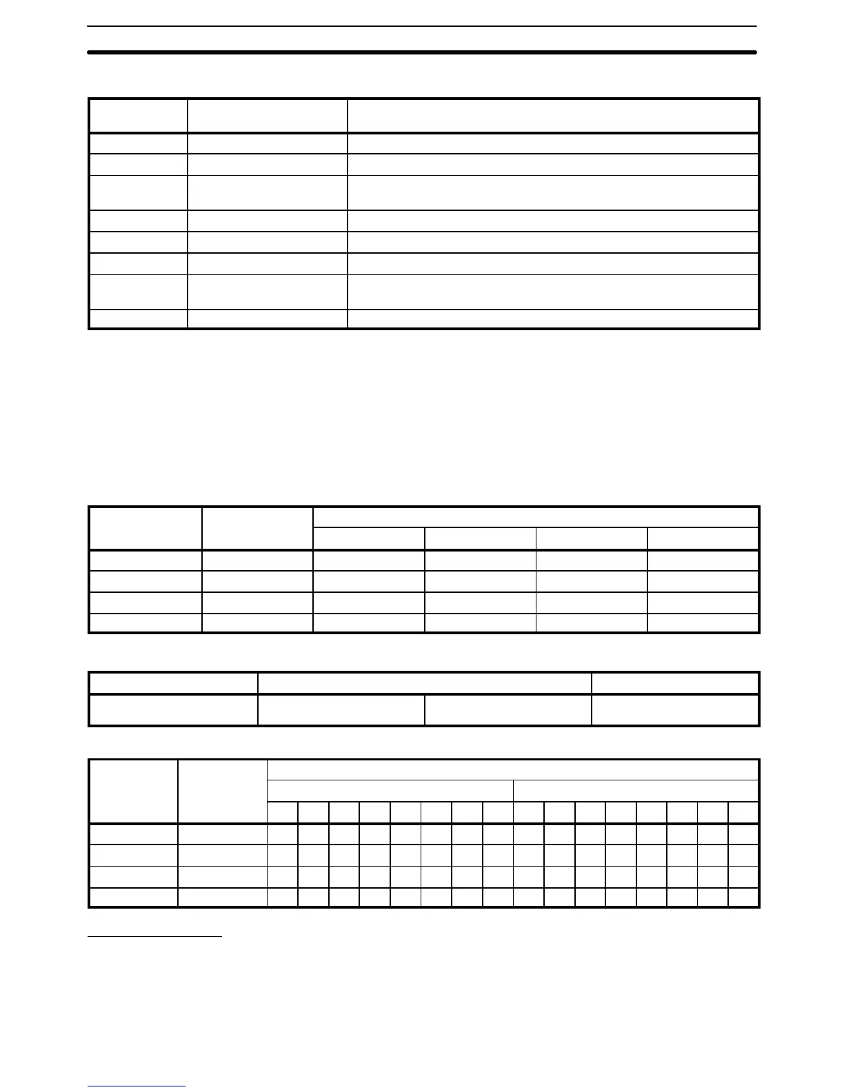
Completion
code
Name Meaning
00 Normal end Data transfer was completed successfully.
01 Parameter error SEND(90)/RECV(98) instruction operands are not within specified ranges.
02 Transmission impossible The System was reset during execution of the instruction or the destination
node is not in the System.
03 Busy error The destination node is busy and cannot receive the transfer.
04 Transmission error The line server token was not received.
05 Loop error An error occurred in the transmission loop.
06 No response Destination node does not exist or response was not received within the
time limit.
07 Response error Incorrect response format.
SYSMAC LINK/SYSMAC NET Link Data link status is output to SR 238
through SR 241 for the operating level 0 data link, and to SR 242 through SR
245 for the operating level 1 data link in the SYSMAC NET Link or SYSMAC
LINK System.
The meaning of each bit in these areas differs depending on whether the
data link is in a SYSMAC LINK System or SYSMAC NET Link System, as
shown below.
SYSMAC LINK Systems
Level 0 Level 1 Bits
00 to 03 04 to 07 08 to 11 12 to 15
SR 238 SR 242 Node 1 Node 2 Node 3 Node 4
SR 239 SR 243 Node 5 Node 6 Node 7 Node 8
SR 240 SR 244 Node 9 Node 10 Node 11 Node 12
SR 241 SR 245 Node 13 Node 14 Node 15 Node 16
Each of the above sets of four bits operates as shown below.
Leftmost bit Middle bits Rightmost bit
ON when data link is active. ON when there is a data
communications error.
ON when there is a PC
error.
ON when PC is in RUN
mode.
SYSMAC NET Link Systems
Level 0 Level 1 Bit numbers in header/Registration number in the data link table
PC Error Flags PC Run Flags
00 01 02 03 04 05 06 07 08 09 10 11 12 13 14 15
SR 238 SR 242 1 2 3 4 5 6 7 8 1 2 3 4 5 6 7 8
SR 239 SR 243 9 10 11 12 13 14 15 16 9 10 11 12 13 14 15 16
SR 240 SR 244 17 18 19 20 21 22 23 24 17 18 19 20 21 22 23 24
SR 241 SR 245 25 26 27 28 29 30 31 32 25 26 27 28 29 30 31 32
PC Link Systems
When the PC belongs to a PC Link System, words 247 through 250 are used
to monitor the operating status of all PC Link Units connected to the PC Link
System. This includes a maximum of 32 PC Link Units. If the PC is in a Multi-
level PC Link System, half of the PC Link Units will be in a PC Link Subsys-
Data Link Status
PC Link Unit Error and Run
Flags
SR Area Section 3-4