103
B: Bit
IR, SR, AR, HR, TC, LR
OR – OR
B
B: Bit
IR, SR, AR, HR, TC, LR
OR NOT – OR NOT
B
There is no limit to the number of any of these instructions, or restrictions in
the order in which they must be used, as long as the memory capacity of the
PC is not exceeded.
These six basic instructions correspond to the conditions on a ladder dia-
gram. As described in Section 4 Writing and Inputting the Program, the
status of the bits assigned to each instruction determines the execution con-
ditions for all other instructions. Each of these instructions and each bit ad-
dress can be used as many times as required. Each can be used in as many
of these instructions as required.
The status of the bit operand (B) assigned to LD or LD NOT determines the
first execution condition. AND takes the logical AND between the execution
condition and the status of its bit operand; AND NOT, the logical AND be-
tween the execution condition and the inverse of the status of its bit operand.
OR takes the logical OR between the execution condition and the status of its
bit operand; OR NOT, the logical OR between the execution condition and
the inverse of the status of its bit operand. The ladder symbol for loading TR
bits is different from that shown above. Refer to 4-3-3 Ladder Instructions for
details.
Flags There are no flags affected by these instructions.
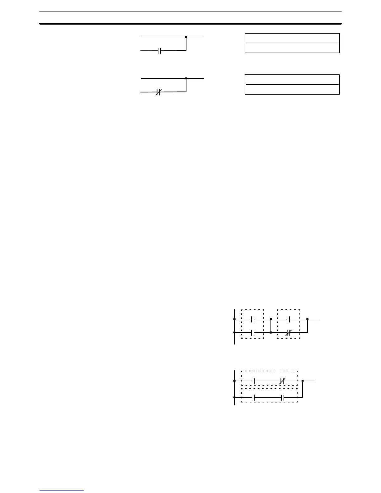
5-6-2 AND LOAD and OR LOAD
Ladder Symbol
AND LOAD – AND LD
00002
00003
00000
00001
Ladder Symbol
OR LOAD – OR LD
00000 00001
00002 00003
When instructions are combined into blocks that cannot be logically com-
bined using only OR and AND operations, AND LD and OR LD are used.
Whereas AND and OR operations logically combine a bit status and an exe-
cution condition, AND LD and OR LD logically combine two execution condi-
tions, the current one and the last unused one.
Limitations
Description
Description
Ladder Diagram Instructions Section 5-6