22
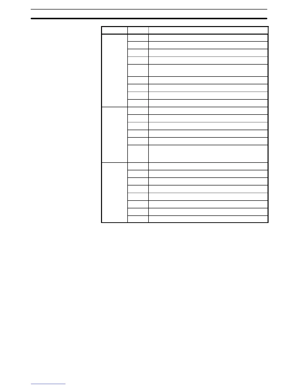
Word(s) FunctionBit(s)
253 00 to 07 FAL number output area.
08 Low Battery Flag
09 Cycle Time Error Flag
10 I/O Verification Error Flag
11 Host Computer to rack-mounting Host Link Unit Level 0
Error Flag
12 Remote I/O Error Flag
13 Normally ON Flag
14 Normally OFF Flag
15 First cycle
254 00 1-minute clock pulse bit
01 0.02-second clock pulse bit
02 to 06 Reserved for function expansion. Do not use.
07 Step Flag
08 to 14 Reserved for function expansion. Do not use.
15 Special Unit Error Flag (Special I/O, PC Link, Host Link,
Remote I/O Master, SYSMAC NET Link, and SYSMAC
LINK)
255 00 0.1-second clock pulse bit
01 0.2-second clock pulse bit
02 1.0-second clock pulse bit
03 Instruction Execution Error (ER) Flag
04 Carry (CY) Flag
05 Greater Than (GR) Flag
06 Equals (EQ) Flag
07 Less Than (LE) Flag
3-4-1 Remote I/O Systems
SR 25312 turns ON to indicate an error has occurred in Remote I/O Sys-
tems. The ALARM/ERROR indicator will flash, but PC operation will continue.
SR 251, as well as AR 0014 and AR 0015, contain information on the source
and type of error. The function of each bit is described below. Refer to Optical
and Wired Remote I/O System Manuals for details.
If there are errors in more than one Remote I/O Unit, word 251 will contain
error information for only the first one. Data for the remaining Units will be
stored in memory and can be accessed by turning the Error Check bit ON
and OFF. Be sure to record data for the first error, which will be cleared when
data for the next error is displayed.
Not used.
Remote I/O Error Flag: Bit 03 turns ON when an error has occurred in a Re-
mote I/O Unit.
The content of bits 04 to 06 is a 3-digit binary number (04: 2
0
, 05: 2
1
, 06: 2
2
)
and the content of bits 08 to 15 is a 2-digit hexadecimal number (08 to 11:
16
0
, 12 to 15: 16
1
).
Bit 00 - Error Check Bit
Bits 01 and 02
Bit 03
Bits 04 to 15
SR Area Section 3-4