107
the set input; R, the reset input. KEEP(11) operates like a latching relay that
is set by S and reset by R.
When S turns ON, the designated bit will go ON and stay ON until reset, re-
gardless of whether S stays ON or goes OFF. When R turns ON, the desig-
nated bit will go OFF and stay OFF until reset, regardless of whether R stays
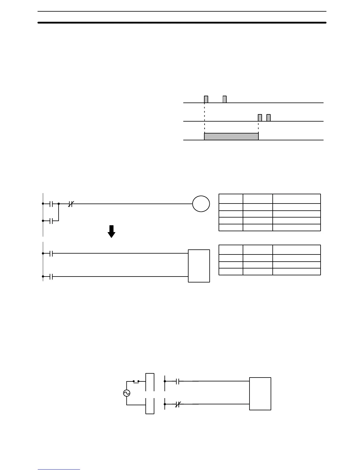
ON or goes OFF. The relationship between execution conditions and
KEEP(11) bit status is shown below.
S execution condition
R execution condition
Status of B
KEEP(11) operates like the self-maintaining bit described in 4-7-3 Self-main-
taining Bits. The following two diagrams would function identically, though the
one using KEEP(11) requires one less instruction to program and would
maintain status even in an interlocked program section.
00002 00003
00500
00002
00003
00500
S
R
KEEP(11)
B
Address Instruction Operands
Address Instruction Operands
00000 LD 00002
00001 OR 00500
00002 AND NOT 00003
00003 OUT 00500
00000 LD 00002
00001 LD 00003
00002 KEEP(11) 00500
Flags There are no flags affected by this instruction.
Exercise caution when using a KEEP reset line that is controlled by an exter-
nal normally closed device. Never use an input bit in an inverse condition on
the reset (R) for KEEP(11) when the input device uses an AC power supply.
The delay in shutting down the PC’s DC power supply (relative to the AC
power supply to the input device) can cause the designated bit of KEEP(11)
to be reset. This situation is shown below.
A
Input Unit
A
NEVER
S
R
KEEP(11)
B
Bits used in KEEP are not reset in interlocks. Refer to the 5-8 INTERLOCK –
and INTERLOCK CLEAR IL(02) and ILC(03) for details.
Precautions
Bit Control Instructions Section 5-7