196
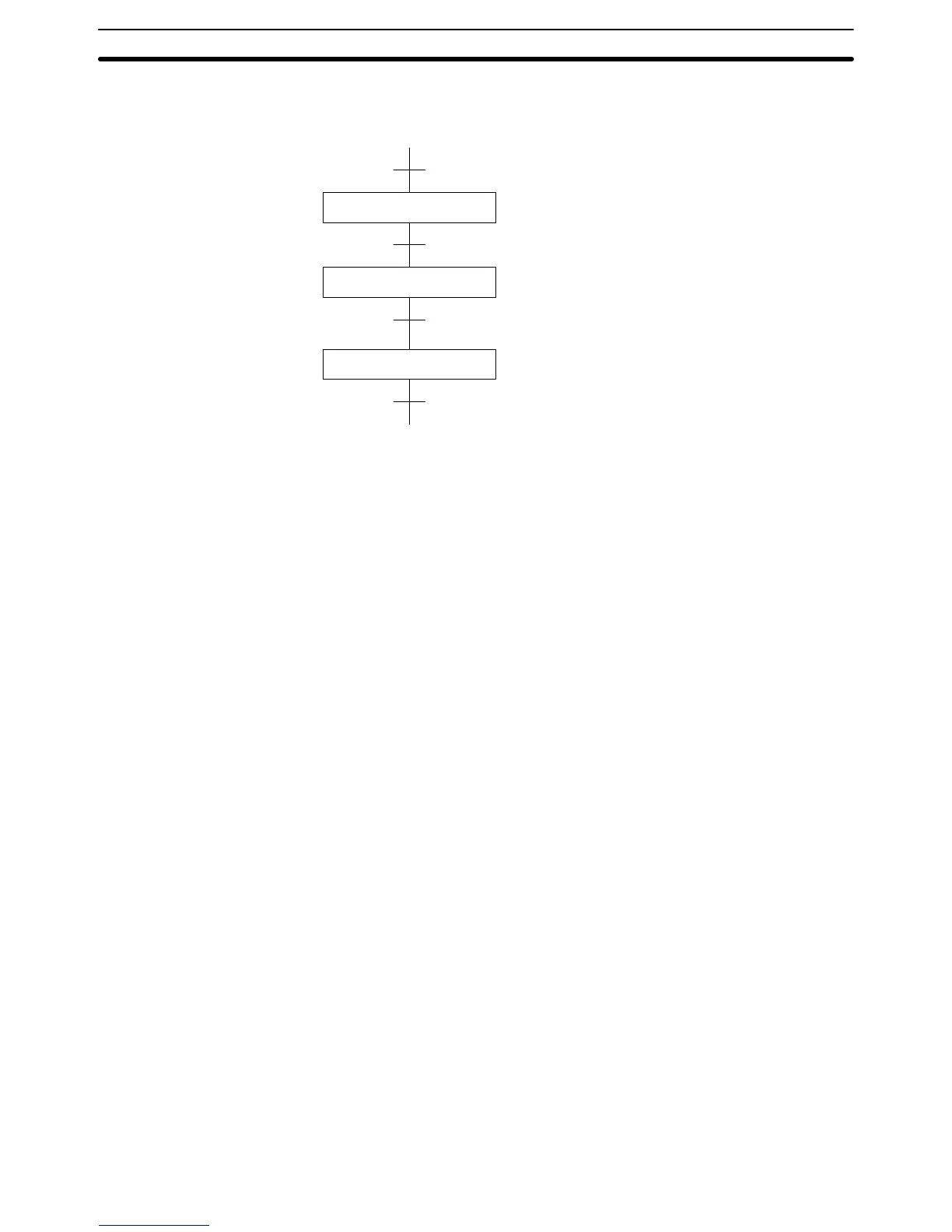
The following diagram demonstrates the flow of processing and the switches
that are used for execution control.
Process A
Process B
Process C
Loading
Part Installation
Inspection/discharge
SW1
SW2
SW3
SW4
The program for this process, shown below, utilizes the most basic type of
step programming: each step is completed by a unique SNXT(09) that starts
Step Instructions Section 5-21