Y
0
Y
2
Y
1
Y
3
Y
4
Y
m
X
0
X
1
X
2
X
3
X
4
X
m
X
Y
209
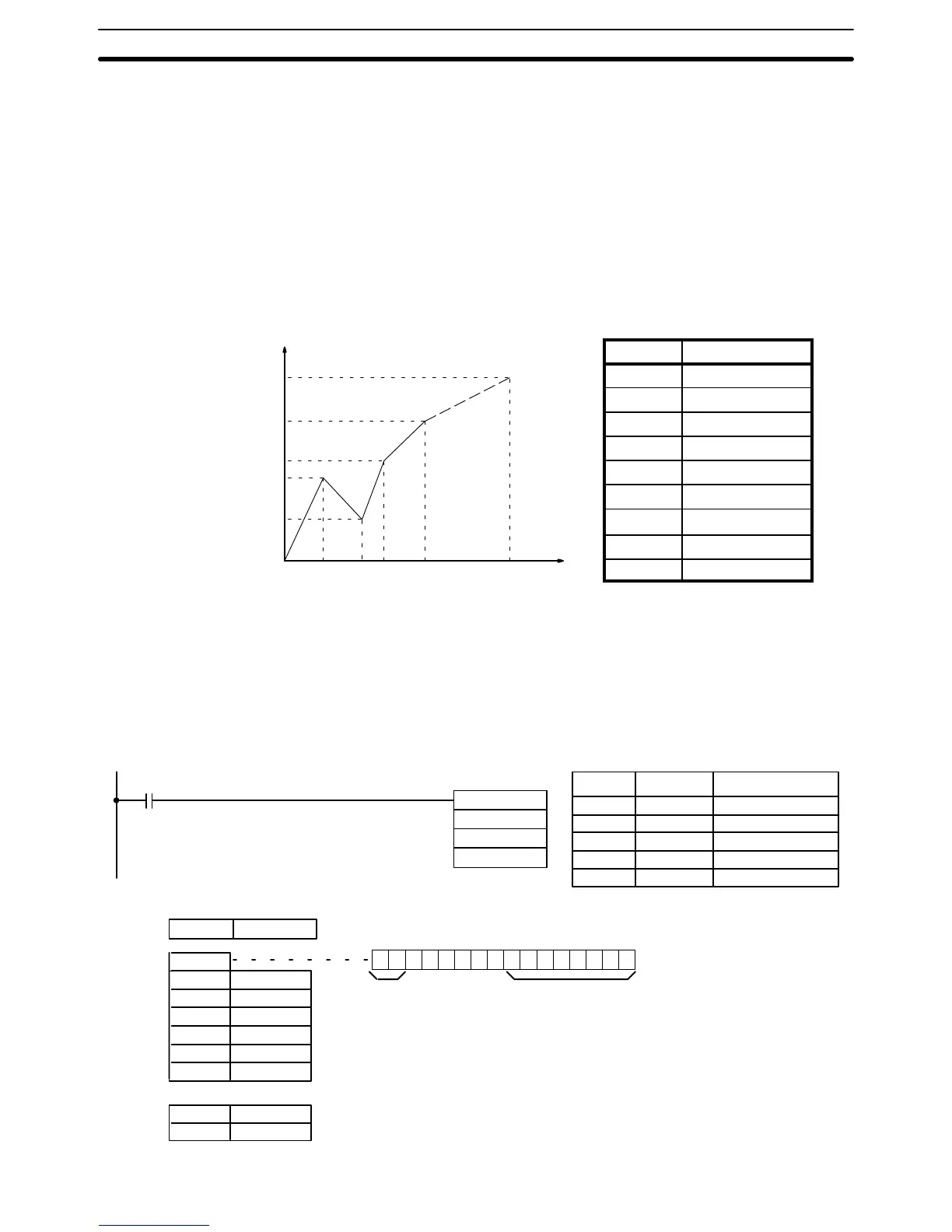
VCAL(69) linear approximation is specified when C is a memory address.
Word C is the first word of the continuous block of memory containing the
linear approximation data.
The content of word C specifies the number of line segments in the approxi-
mation, and whether the input and output are in BCD or BIN form. Bits 00 to
07 contain the number of line segments less 1, m–1, as binary data. Bits 14
and 15 determine, respectively, the output and input forms: 0 specifies BCD
and 1 specifies BIN.
Enter the coordinates of the m+1 end-points, which define the m line seg-
ments, as shown in the following table. Enter all coordinates in BIN form. Do
not allow the data block to overlap the RAM and EEPROM sections of the
DM area. The EEPROM section begins at DM1000.
Word Coordinate
C+1 X
m
(max. X value)
C+2 Y
0
C+3 X
1
C+4 Y
1
C+5 X
2
C+6 Y
2
↓ ↓
C+(2m+1) X
m
C+(2m+2) Y
m
The following example demonstrates the construction of a linear approxima-
tion with 12 line segments. The block of data is continuous, as it must be,
from DM 0000 to DM 0026 (C to C + (2 × 12 + 2)). The input data is taken
from IR 010, and the result is output to IR 011.
DM 0000 $C00B
DM 0001 $05F0 X
12
DM 0002 $0000 Y
0
DM 0003 $0005 X
1
DM 0004 $0F00 Y
1
DM 0005 $001A X
2
DM 0006 $0402 Y
2
↓↓↓
DM 0025 $05F0 X
12
DM 0026 $1F20 Y
12
VCAL(69)
DM 0000
010
011
00000
1 1 0 0 000000001011
Bit
15
Bit
00
(Output and
input both BIN)
(m–1 = 11: 12 line
segments)
Content Coordinate
Address Instruction Operands
00000 LD 00000
00001 VCAL(69)
DM 0000
010
011
Linear Approximation
Special Instructions Section 5-22