19
signed as I/O bits can be used as work bits. IR area work bits are reset when
power is interrupted or PC operation is stopped.
If a Unit brings inputs into the PC, the bit assigned to it is an input bit; if the
Unit sends an output from the PC, the bit is an output bit. To turn on an out-
put, the output bit assigned to it must be turned ON. When an input turns on,
the input bit assigned to it also turns ON. These facts can be used in the pro-
gram to access input status and control output status through I/O bits.
Input bits can be used to directly input external signals to the PC and can be
used in any order in programming. Each input bit can also be used in as
many instructions as required to achieve effective and proper control. They
cannot be used in instructions that control bit status, e.g., the Output, Differ-
entiation Up, and Keep instructions.
Output bits are used to output program execution results and can be used in
any order in programming. Because outputs are refreshed only once during
each cycle (i.e., once each time the program is executed), any output bit can
be used in only one instruction that controls its status, including OUT,
KEEP(11), DIFU(13), DIFD(14) and SFT(10). If an output bit is used in more
than one such instruction, only the status determined by the last instruction
will actually be output from the PC.
See 5-13-1 Shift Register - SFT(10) for an example that uses an output bit in
two ‘bit-control’ instructions.
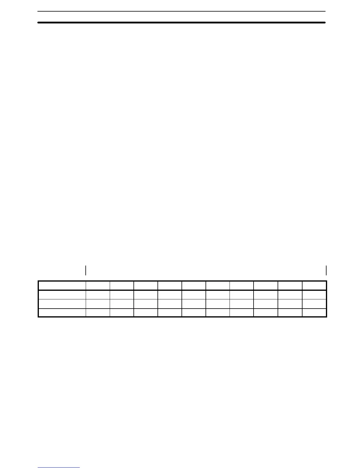
I/O words are allocated to the CPU Rack and Expansion I/O Racks by slot
position. One I/O word is allocated to each slot, as shown in the following
table. Since each slot is allocated only one I/O word, a 3-slot rack uses only
the first 3 words, a 5-slot rack uses only the first 5 words, and an 8-slot rack
uses only the first 8 words. Words that are allocated to unused or nonexistent
slots are available as work words.
←
Left side of rack Right side of a 10-slot rack →
Rack Slot 1 Slot 2 Slot 3 Slot 4 Slot 5 Slot 6 Slot 7 Slot 8 Slot 9 Slot 10
CPU IR 000 IR 001 IR 002 IR 003 IR 004 IR 005 IR 006 IR 007 IR 008 IR 009
1
st
Expansion IR 010 IR 011 IR 012 IR 013 IR 014 IR 015 IR 016 IR 017 IR 018 IR 019
2
nd
Expansion IR 020 IR 021 IR 022 IR 023 IR 024 IR 025 IR 026 IR 027 IR 028 IR 029
Up to ten Special I/O Units may be mounted in any slot of the CPU Rack or
Expansion I/O Racks. Up to five Slave Racks may be used, whether one or
I/O Words
Input Bit Usage
Output Bit Usage
Word Allocation for Racks
Allocation for Special I/O
Units and Slave Racks
IR Area Section 3-3