Data Areas Appendix E
330
Dedicated Bits
Most of the bits in the SR and AR area are dedicated for specific purposes. These are summarized in the fol-
lowing tables. Refer to 3-4 SR Area and 3-5 AR Area for details.
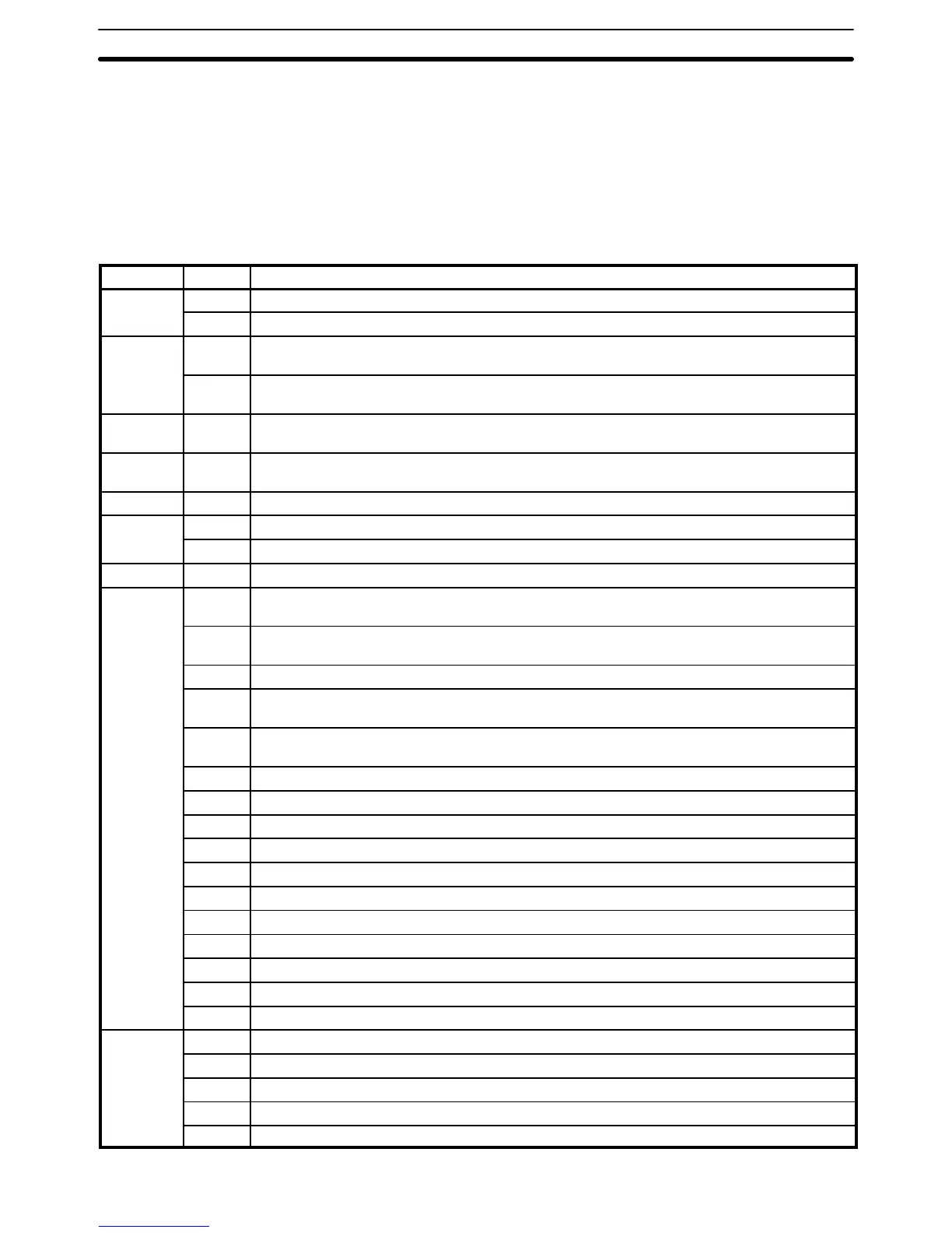
SR Allocations
As a rule, SR area bits can be used only for the purposes for which they are dedicated. The SR area contains
flags and control bits used for monitoring PC operation, accessing clock pulses, and signalling errors. SR area
word addresses range from 236 through 255; bit addresses, from 23600 through 25507.
Word(s) Bit(s) Function
236 00 to 07 Node loop status output area for operating level 0 of SYSMAC NET Link System
08 to 15 Node loop status output area for operating level 1 of SYSMAC NET Link System
237 00 to 07 Completion code output area for operating level 0 following execution of SEND(90)/RECV(98)
SYSMAC LINK/SYSMAC NET Link System
08 to 15 Completion code output area for operating level 1 following execution of SEND(90)/RECV(98)
SYSMAC LINK/SYSMAC NET Link System
238 to 241 00 to 15 Data link status output area for operating level 0 of SYSMAC LINK or SYSMAC NET Link Sys-
tem
242 to 245 00 to 15 Data link status output area for operating level 1 of SYSMAC LINK or SYSMAC NET Link Sys-
tem
246 00 to 15 Not used.
247 to 250 00 to 07 PC Link Unit Run Flags or data link status for operating level 1
08 to 15 PC Link Unit Error Flags or data link status for operating level 1
251 00 to 15 Remote I/O Error Flags
252 00 SEND(90)/RECV(98) Error Flag for operating level 0 of SYSMAC LINK/SYSMAC NET Link
System
01 SEND(90)/RECV(98) Enable Flag for operating level 0 of SYSMAC LINK/SYSMAC NET Link
System
02 Operating Level 0 Data Link Operating Flag
03 SEND(90)/RECV(98) Error Flag for operating level 1 of SYSMAC LINK/SYSMAC NET Link
System
04 SEND(90)/RECV(98) Enable Flag for operating level 1 of SYSMAC LINK/SYSMAC NET Link
System
05 Operating Level 1 Data Link Operating Flag
06 Host Computer to Rack-mounting Host Link Unit Level 1 Error Flag
07 Rack-mounting Host Link Unit Level 1 Restart Bit
08 CPU-mounting Host Link Unit Error Flag
09 CPU-mounting Host Link Unit Restart Bit
10 Not used.
11 Forced Status Hold Bit (CPU11-E only)
12 I/O Status Hold Bit
13 Rack-mounting Host Link Unit Level 0 Restart Bit
14 Not used.
15 Output OFF Bit
253 00 to 07 FAL number output area.
08 Low Battery Flag
09 Cycle Time Error Flag
10 I/O Verification Error Flag
11 Host Computer to rack-mounting Host Link Unit Level 0 Error Flag