Type Pin No. Cable color Mark Signal
Pair 3 2 Green Black Encoder B+
7 Green Red Encoder B-
Pair 4 3 Orange Black Encoder C+
8 Orange Red Encoder C-
Pair 5 15 Gray Black OutFlagB
14 Gray Red GND
*1. Inside the connector, Pin 1 and Pin 5 are short-circuited.
*2. Inside the connector, Pin 6 and Pin 10 are short-circuited.
Note The cable shield is connected to the connector shell of the encoder connector.
When using this cable, set to OutFlagD = 1, and disable the serial encoder DA
T terminating resistance.
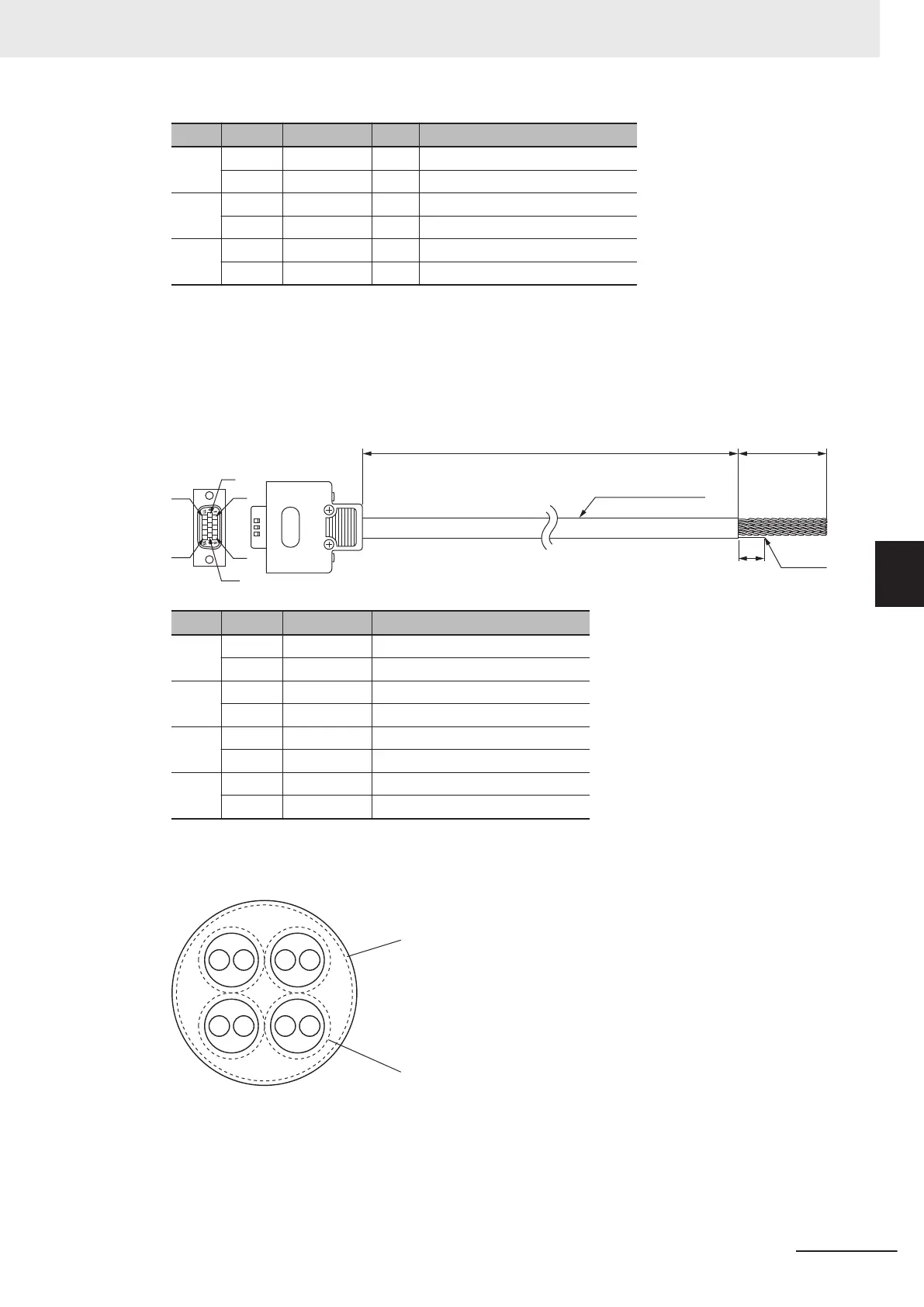
For Sinusoidal Encoder
Shield
1
0
3,000 35
24AWG x 4 Pairs
6
1
5
10
15
11
Type Pin No. Cable color Signal
Pair 1 11 Black Encoder Power Supply (+5 VDC)
13 Blue Encoder Power Supply (GND)
Pair 2 1 Black SIN+
6 Red SIN-
Pair 3 2 Black COS+
7 White COS-
Pair 4 3 Black INDEX+
8 Green INDEX-
Note The cable shield consists of an overall shield and pair shields.
The overall shield is connected to the connector shell of the encoder connector
.
The pair shields are connected to the Encoder Power Supply (GND) pin.
Overall shield
Pair shield
5 Wiring
5-21
CK3M-series Programmable Multi-Axis Controller User's Manual Hardware (O036)
5-3 Axis Interface Unit Wiring
5
5-3-1 Encoder Connector Wiring

 Loading...


