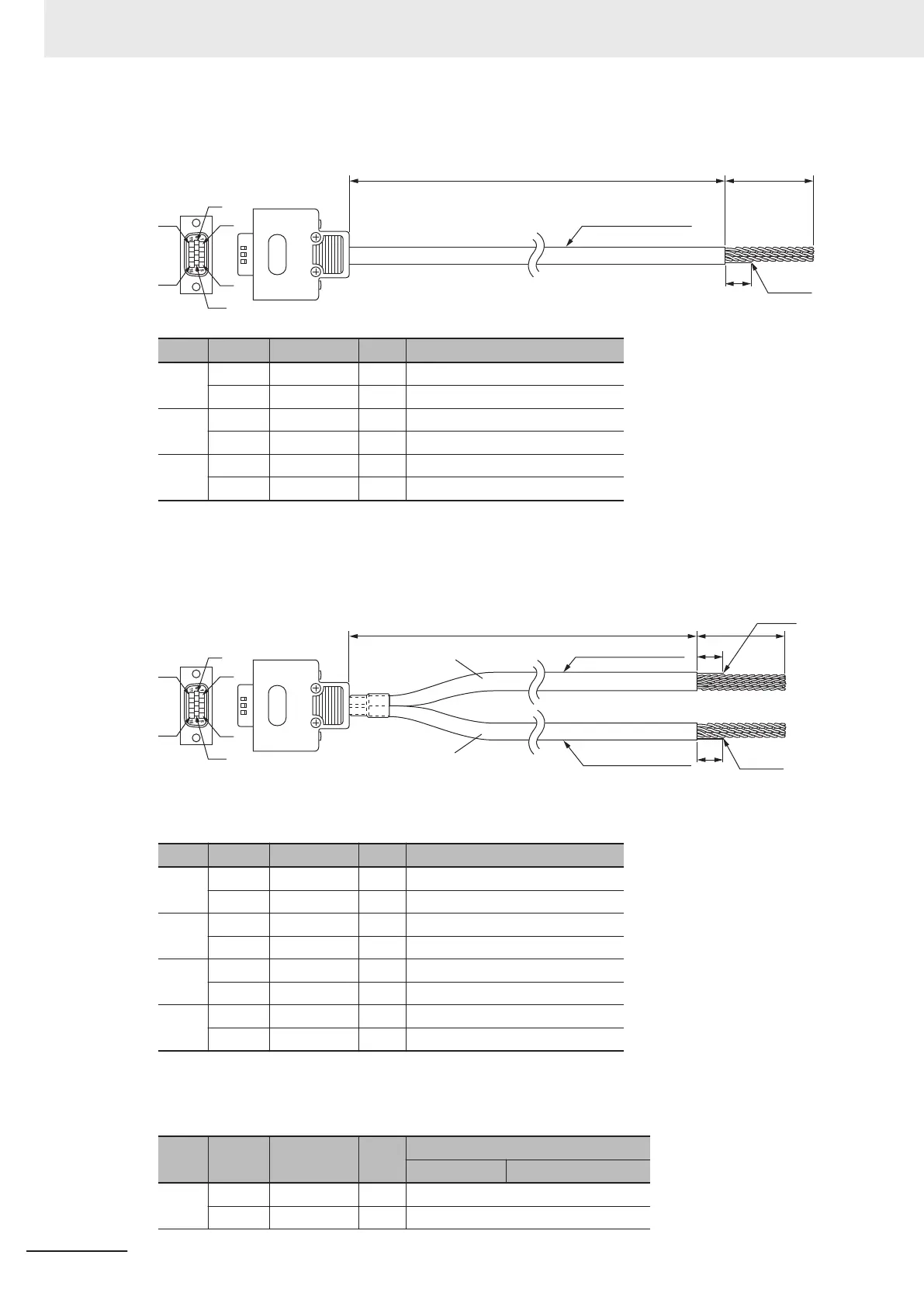
For Serial Encoder
Shield
1
0
3000 35
24AWG x 3 Pairs
6
1
5
10
15
11
Type Pin No. Cable color Mark Signal
Pair 1 12 Blue Black Encoder Power Supply (+5 VDC)
14 Blue Red Encoder Power Supply (GND)
Pair 2 4 Pink Black Encoder CLK+
9 Pink Red Encoder CLK-
Pair 3 5 Green Black Serial Encoder DAT+
10 Green Red Serial Encoder DAT-
Note The cable shield is connected to the connector shell of the encoder connector.
For “Digital Quadrature Encoder + UVW Signal” or “Digital Quadrature En-
coder + Serial Encoder”
Shield
Shield
Cable 1
Cable 2
3,000
35
10
10
24AWG × 4 Pairs
24AWG × 3 Pairs
6
1
5
10
15
11
Cable 1
Type Pin No. Cable color Mark Signal
Pair 1 11 Blue Black Encoder Power Supply (+5 VDC)
13 Blue Red Encoder Power Supply (GND)
Pair 2 1 Pink Black Encoder A+
6 Pink Red Encoder A-
Pair 3 2 Green Black Encoder B+
7 Green Red Encoder B-
Pair 4 3 Orange Black Encoder C+
8 Orange Red Encoder C-
Note The cable shield is connected to the connector shell of the encoder connector.
Cable 2
Type Pin No. Cable color Mark
Signal
U, V, W Serial Encoder
Pair 1 12 Blue Black Encoder Power Supply (+5 VDC)
14 Blue Red Encoder Power Supply (GND)
5 Wiring
5-22
CK3M-series Programmable Multi-Axis Controller User's Manual Hardware (O036)

 Loading...


