Omron TM Collaborative Robot S Series: TM12S and TM14S Hardware Installation Manual
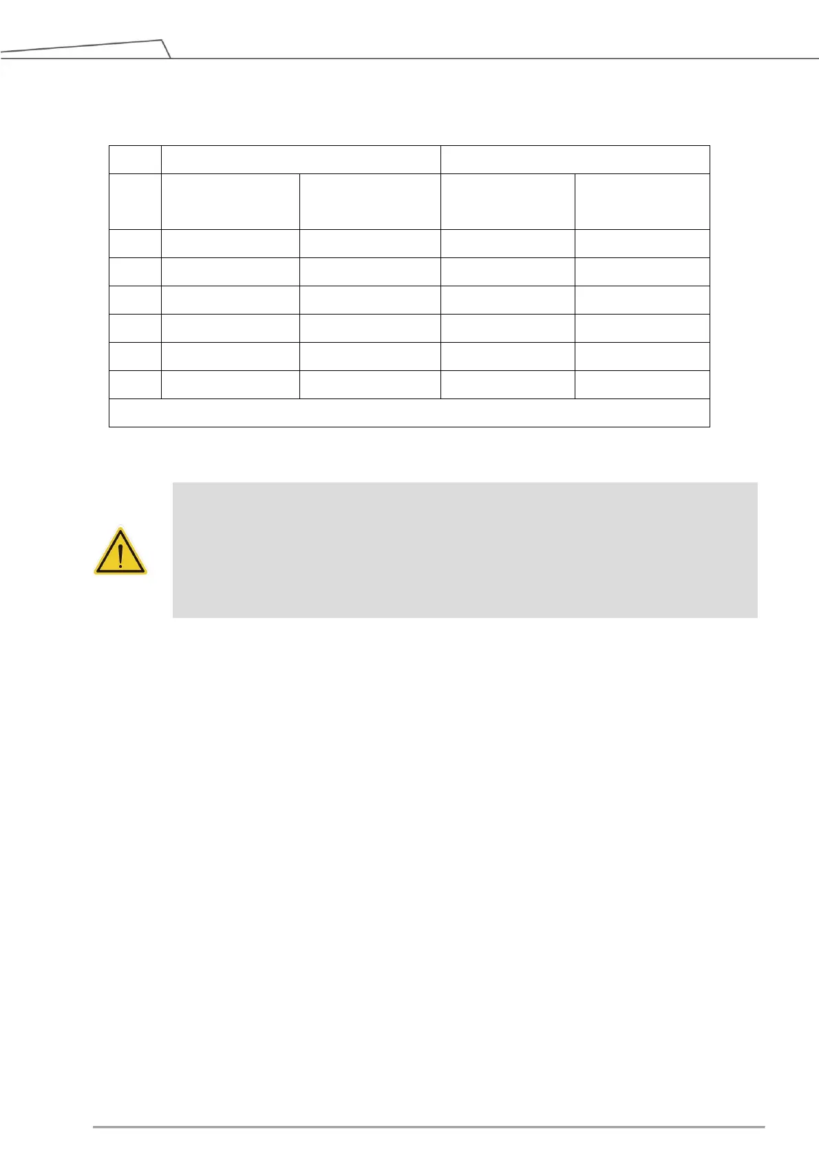
torque may reduce the life of the robot or damage the robot.
Limit for repeated
peak torque
Limit for repeated
peak torque
Table 4: Rated Torque and Limit for Repeated Peak Torque of TM12S and TM14S Robot Series
WARNING:
Use the total weight of the end-effector and the payload to stay within the payload rating of
the robot. Ensure that the system never exceeds that maximum payload. Users should
perform a full risk assessment that includes the end-effector and payload samples to prevent
hazards such as shocks, vibrations, collisions, entanglements, stabbings, and piercings to
secure the entire system.
4.2.1.5 Robot Arm Installation
The robot can be secured to another surface with the use of four M10 screws and washers. The
mounting pattern is shown below. The recommended tightening torque is 40 Nm.
Optional - Two openings for 6 ㎜ position pins are provided for more secure position mounting.
Ensure the strength of the mounting surface and its surround area before installations for upside down
mounting and side mounting such as on the ceiling or the wall. Wherever the installation takes place,
the robot setting remains equivalent.
 Loading...