Omron TM Collaborative Robot S Series: TM12S and TM14S Hardware Installation Manual
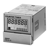
Figure 36: The Wiring Diagram Example of PNP Output Type Safety Device
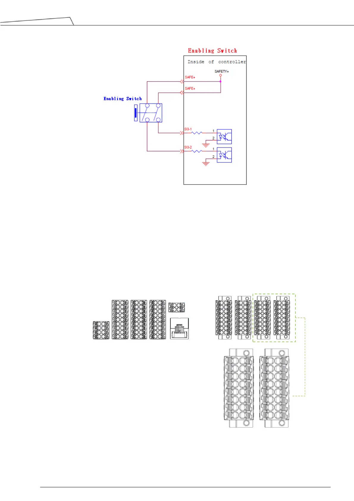
5.3.1.2 Safety Output Connector
1. SO 0-1/ SO 0-2 to SO 7-1/ SO 7-2 are user defined Safety Output Port. Safety functions can be
assigned to these ports.
For details about the safety functions, please refer to the Safety Manual.
Figure 37: Safety Output Connector
 Loading...