Omron TM Collaborative Robot S Series: TM12S and TM14S Hardware Installation Manual
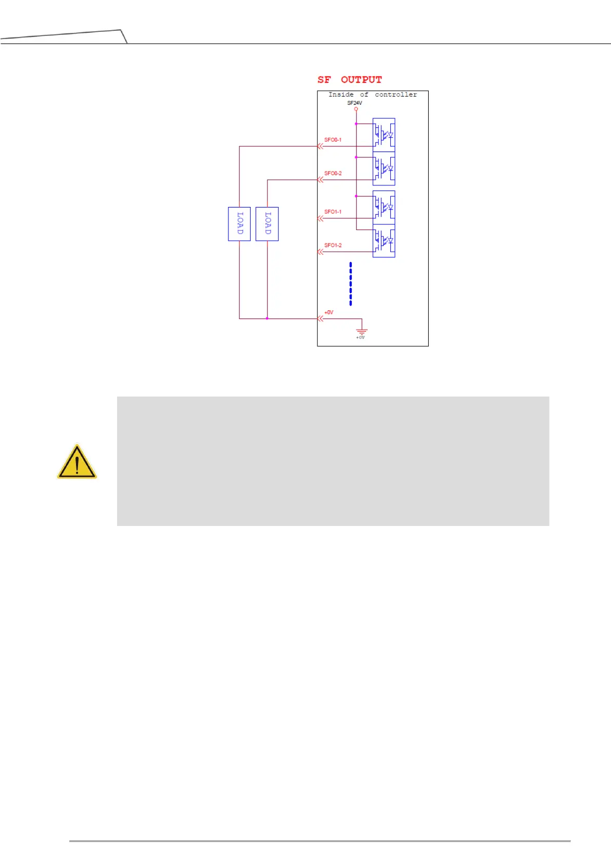
Figure 38: Safety Output Connector Wiring Diagram
5.3.2 Power Connector
1. During boot, the control box will check for an external 24V input. If none is found, then it will switch to
the internal 24V supply.
2. The control box itself offers a 24V/2A output. If the 24V load exceeds 2A, it enters Safe Mode and
disables the 24V output.
3. EX24V provides an external 24V input port. If the load exceeds 2A an external power supply can be
used instead. The load on EX24V must not exceed 3.5A.
DANGER:
1. Do not connect the safety signals to a non-safety device without the fulfilled safety level.
Failure to do so may result in injury or death due to a malfunction of the safety stop.
2. All safety I/Os come with dual redundant channel connectors. Maintain both redundant
channels while they are paired and connected, so that any single fault on either channel
will not result in failure of safety functions.
3. Before putting the robot to use, be sure to check the safety functions and check the
safety functions on a regular basis.
 Loading...