Omron TM Collaborative Robot S Series: TM12S and TM14S Hardware Installation Manual
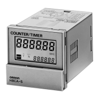
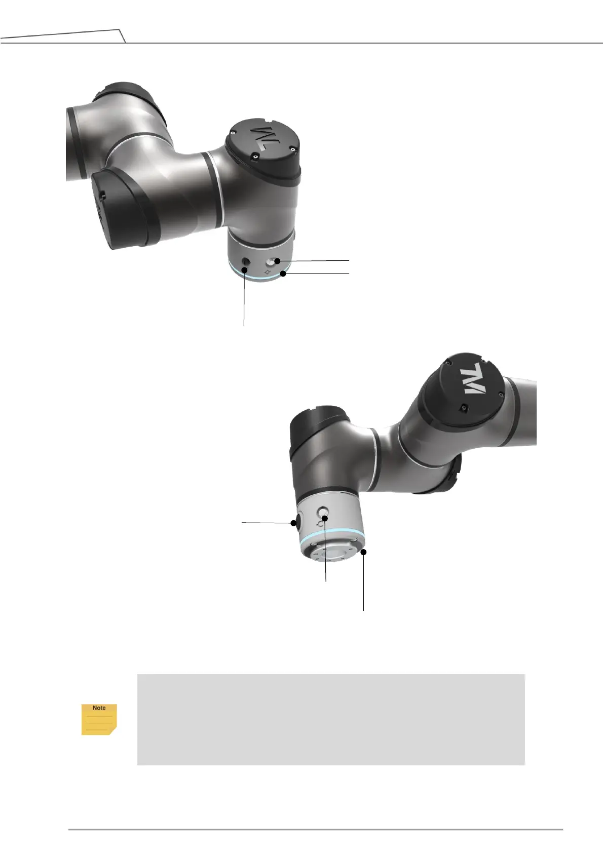
Figure 19: References of TM12S-X / TM14S-X End Module Components
NOTE:
There are two contacts in the Enabling Switch that are designed to operate
independently. Press the edge of the Enabling Switch turns on one contact earlier
than the other contact, causing discrepancy to the enable signals. A safety
protection mechanism will be initiated after the discrepancy occurs. Users are
required to resume following the instruction log from HMI.
4.2.2.2 Flange Surface of the Robot End
Flange (ISO 9409-1-50-4-M6)
FREE Button
(3-position
Enabling Switch)
 Loading...